Wireshark Analysis

Wireshark Analysis
Denial of Service Attacks (DoS-DDoS) Wireshark Analysis
Hello, in this article, I will analyze denial of service attacks known as DoS and DDoS with Wireshark.
Wireshark
Wireshark is open source software used as a network analysis tool. Wireshark can capture, inspect and analyze network traffic so it can be used to diagnose network problems, detect security threats or monitor network performance.
For detailed information: https://www.wireshark.org/
You can follow the steps below to install Wireshark on your computer. Please note that these steps may vary depending on your operating system and intended use. Here are the general steps to install Wireshark:
For Windows Operating System:
- Visit Wireshark's Official Website: It is recommended to download Wireshark from its official website. You can access the official website at: https://www.wireshark.org/
- Go to Download Page: On the home page, click on the "Download" or "Download" link.
- Select Download Options: Select the Wireshark version for Windows and begin the download. The file you download will have the .exe extension.
- Run the Installation Wizard: Run the downloaded .exe file. May require Windows UAC (User Account Control) permission. Grant the permission and continue with the installation process.
- Set Installation Options: During installation, you can choose whether to install components such as Wireshark and WinPcap (Npcap in some versions). It is usually a good option to accept the recommended settings.
- Complete the Installation: Follow the necessary steps to complete the installation process. Once the installation is complete, you will have the option to launch Wireshark.
- Launch Wireshark: Once the installation is complete, launch Wireshark. You can now capture and analyze network traffic.
For Linux Operating System:
Wireshark is available in the repositories of many Linux distributions, so you can install the package using the commands below. For example, on a Debian or Ubuntu based system:
sudo apt update
sudo apt install wireshark
Administrator permission with sudo may be required during installation. Additionally, in order to use Wireshark, it may be necessary to add the user to the "wireshark" group or start it with sudo.
For Mac OS:
To use Wireshark on Mac OS X, you can download and install a DMG file from the official website. You should frequently follow the instructions during installation.
Once you install Wireshark, you can start using it to capture and analyze network traffic. Remember that monitoring network traffic may require certain permissions and you must do so in a legal and ethical manner.
DoS â€" DDoS
Denial of Service (DoS) and Distributed Denial of Service (DDoS) attacks are types of cyber attacks that aim to temporarily or permanently disrupt the ability to provide services to computer systems or networks.
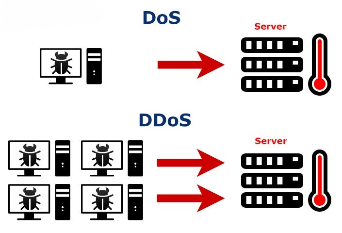
A DoS (Denial of Service) attack is an attempt to make traffic from a single source unusable. DDoS (Distributed Denial of Service) attack is an attempt to make coordinated traffic coming from many sources unusable. The main difference is that DoS comes from a single source whereas DDoS comes from multiple sources. DDoS is a larger and more effective type of attack.
You can use the hping3 tool on a Linux machine to perform these attacks in your own lab environment. In addition, the DoS Attack Framework tool offers you an interactive interface to perform DoS attacks.
TCP Attacks
TCP (Transmission Control Protocol) is a communication protocol used to ensure reliable and sequential data transmission between computers. The way TCP works is managed using control pointers called flags. Explanations of TCP's operating principles and flags are given:
- Initialization (SYN â€" Synchronize): The client side sends a packet containing a "SYN" flag to initiate the connection.
- Response (SYN-ACK â€" Synchronize Acknowledgment): If the server side accepts the connection, it sends a response containing the "SYN-ACK" flag.
- **Acknowledgment (ACK â€" Acknowledgment):**The client party sends a response containing an "ACK" flag to confirm that the second party has received the acceptance response, and the connection is completed.
- Data Transmission (PSH â€" Push, URG â€" Urgent, FIN â€" Finish, RST â€" Reset): After the connection is established, the parties start data transmission. The data packets to be transmitted are marked with these flags:
- PSH (Push): Indicates that you want the data to be transmitted quickly.
- URG (Urgent): Indicates that it is priority data.
- FIN (Finish): Ends data transmission.
- RST (Reset): Resets and terminates the connection.
TCP uses flags to ensure the order and reliability of sent data. Data packets are transmitted in a specific order, and missing or faulty packets are re-requested.
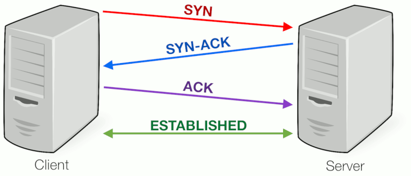
Three Way Handshake
Denial of service attacks using the TCP protocol are attacks that generally aim to consume network or server resources and cause service interruptions. These types of attacks can affect target networks or servers by exploiting vulnerabilities in TCP/IP communications. Here are some denial of service attacks using the TCP protocol:
SYN Flood Attack
In this attack, attackers send a large number of fraudulent connection requests (SYN requests) to the target server. While the target server tries to respond to these requests, it consumes its resources and becomes unable to serve real users.
When we detect a SYN Flood attack with Wireshark, we see many TCP packets with SYN flags sent at very short time intervals.
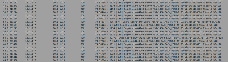
SYN-Flood
RST Flood Attack
Attackers reset existing connections by sending spoofed TCP RST packets to the target server. This may disrupt the functioning of the target server and render services unusable.
When we detect an RST Flood attack with Wireshark, we see many RST flagged TCP packets sent at very short time intervals. It also manipulates the source address and makes it appear as if it comes from different IP addresses.

RST Flood
ACK-PSH Flood Attack
In this type of attack, attackers send large amounts of fake TCP ACK and PSH (Push) packets to the target server. This can consume the server's resources and cause services to slow down.
When we detect an ACK-PSH Flood attack with Wireshark, we see many TCP packets with PSH+ACK flags sent in very short time intervals. It manipulates the source address and makes it appear as if it comes from different IP addresses.
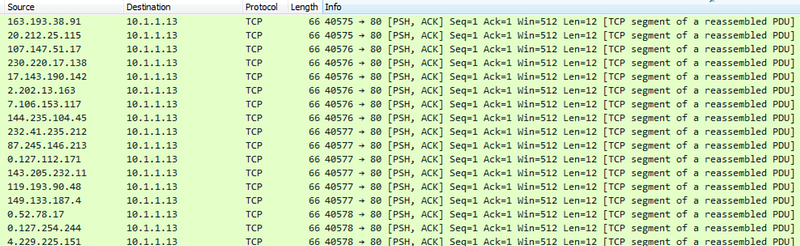
ACK-PSH Flood
ACK Flood Attack
Attackers send large amounts of fake TCP ACK (Acknowledgment) packets to the target server. This can quickly consume the server's resources.
Similar to ACK-PSH, when we look at ACK Floo with wireshark, we see TCP packets with ACK flags sent at very short intervals. The source address was manipulated to appear as coming from a different source.

ACK Flood
These types of attacks create situations where servers and networks are overloaded and can cause service outages. Therefore, targets often use security measures and cybersecurity solutions to detect and defend against attacks. These solutions may include measures such as traffic filtering, firewalls, intrusion detection systems, and load balancing. Additionally, network security policies and good security practices are also important.
UDP Attacks
UDP (User Datagram Protocol) is a communication protocol used for data transmission in IP-based networks. UDP allows data packets to be transmitted quickly and with low latency, but does not guarantee reliable transmission or reception of data. UDP is often used in applications such as audio and video streaming and network gaming.
UDP does not include security and reliability mechanisms like TCP to transmit or receive data securely. Therefore, UDP attacks can be more unpredictable and harder to defend against. Some UDP attacks and their explanations:
UDP Flood Attack
In this type of attack, attackers send a large amount of spoofed UDP packets to the target server. These packets attempt to exhaust the target server's resources and render its services unusable.Such attacks may involve sending packets so fast that the target server cannot respond.
Similar to TCP attacks, when we look at UDP attacks with Wireshark, we see packets sent at very short intervals. The difference is this time there are UDP packets, not TCP. In addition, the source address was manipulated and shown as coming from a different source.
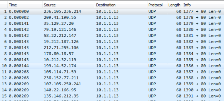
UDP Flood
UDP Fragmentation Attacks
In this type of attack, attackers divide large UDP packets into small pieces and send these pieces to the target server. This may cause the target server to exhaust its resources to reassemble packages.
Protection against UDP attacks may include security measures such as traffic filtering, firewalls, packet balancing, and intrusion detection systems. Additionally, the target server's resources and network traffic should be monitored and intervention should be taken when abnormal situations are detected.
ICMP Attacks
ICMP (Internet Control Message Protocol) is a communication protocol used to perform error notification, network routing information, and other network management functions on an IP network. ICMP attacks aim to disable a service or network by using this protocol for malicious purposes. Below are some of the common ICMP attacks and their descriptions:
Ping Attacks (Ping Flood)
Attackers send large amounts of ICMP Echo Request (ping) requests to the target server. These requests require the target server to respond and may consume the server's resources.
When we examine the network traffic with Wireshark, we see many ICMP echo request packets. These requests came from a single source.
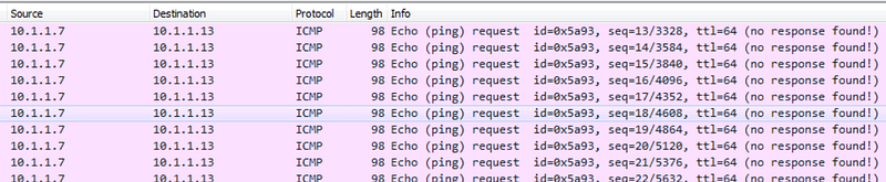
Ping Flood
Smurf Attacks
In this type of attack, attackers send large amounts of ICMP Echo Requests using spoofed source IP addresses. These requests are forwarded to all devices on the network and all devices respond, causing the target server to become overloaded.
When we examine the network traffic with Wireshark, we see many ICMP echo request packets. These requests appear to come from manipulated sources.
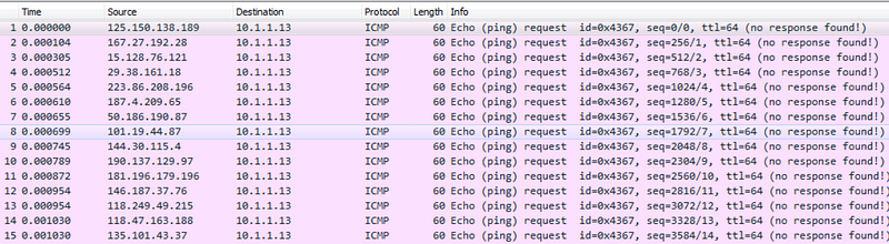
Smurf Attack
ICMP Redirect Attacks
Attackers attempt to spoof devices on the target network with spoofed ICMP Redirect requests. This can be used to redirect network traffic to a malicious server.
ICMP Time Exceeded Attacks
In this type of attack, attackers try to exhaust the target server's resources by sending ICMP Time Exceeded messages. These messages may increase traffic generated by ICMP traffic.
ICMP attacks can overload the target network or server, causing service interruptions. Protection against such attacks may include security measures such as firewalls, IPS (Intrusion Prevention System), ICMP traffic filtering and penetration tests. Additionally, it is important for network administrators to monitor network traffic and detect abnormal activity.
HTTP/HTTPS Attacks
HTTP and HTTPS denial of service (DoS â€" Denial of Service attacks aim to target web servers or web applications and prevent access to these services. Such attacks can cause server overload and service outages. Here are some denial of service attacks against HTTP and HTTPS services:
HTTP Flood Attacks
Attackers send a large number of HTTP requests to the target web server. This can consume the server's resources and cause it to become unavailable.
I found a tool written in Python to perform this attack. Link here. I performed an HTTP flood attack on a web server I set up at my local location.
When we examine the traffic with Wireshark, we see that many HTTP GET packets are sent in very short intervals.
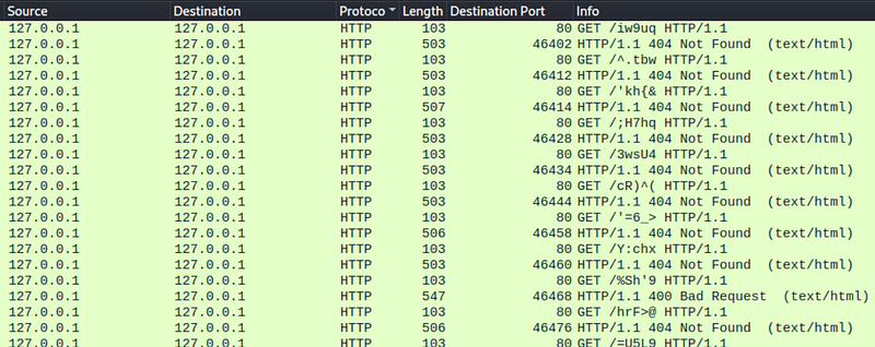
HTTP GET Flood
Slowloris Attacks
Attackers establish a slow connection to the web server and keep that connection open. This may prevent the server from responding to new connections.
SSL/TLS Handshake Attacks
Attackers can exhaust servers' resources by overloading SSL/TLS handshake processes. For this, the target web serverIt must use the HTTPS protocol and have an SSL certificate.
BEAST (Browser Exploit Against SSL/TLS) Attacks
In such attacks, attackers can compromise secure connections by trying to decrypt previously encrypted data. For this, the target web server must use the HTTPS protocol and have an SSL certificate.
Heartbleed Attacks
Heartbleed vulnerability is a type of attack that targets SSL/TLS servers. Attackers can steal sensitive information from the server. Likewise, for this attack, the target web server must use the HTTPS protocol and have an SSL certificate.
Methods of protection against denial of service attacks may include security measures such as traffic filtering, firewalls, load balancing, use of CDN (Content Delivery Network) and service monitoring. It is also important to apply up-to-date software patches and security policies.
DNS Attacks
DNS (Domain Name System) is a service and protocol that translates domain names on the Internet (for example, www.example.com) into IP addresses (for example, 192.0.2.1) and provides this translation process. DNS translates domain names understandable to humans into IP addresses understandable to computers. This allows applications such as internet browsers to convert domain names entered by users into real IP addresses.
DNS
DNS denial of service attacks are cyber attacks that aim to disrupt or interrupt the operation of this service. Denial of service attacks against DNS services can include:
DNS Flood Attacks
Attackers send large numbers of spoofed DNS queries to the target DNS server. The server quickly runs out of resources to process these queries and the DNS service is interrupted.
DNS Amplification Attacks
Attackers send large-sized queries to the DNS server, which trigger larger responses from the DNS server. Responses are routed towards the target server, causing the target server to become overloaded.
DNS Cache Poisoning Attacks
Attackers attempt to insert spoofed data into the target DNS server's cache. This can mislead users by sending false IP addresses to the target's users.
NXDOMAIN Attacks
Attackers exhaust the target's resources by sending fake NXDOMAIN (Domain Not Found) queries to which the target server responds.
DNS denial of service attacks can have serious consequences, such as disrupting internet access or rendering websites unusable. Protecting against such attacks may include measures such as improving the security settings of DNS servers, monitoring and filtering traffic, using DNS security extensions, and maintaining backup DNS servers. It is also important to ensure that DNS servers and infrastructure are up to date and secure.
Macof Attack
MACOF (MAC Flooding) attack is a type of network attack performed on Ethernet networks. This attack is carried out with the aim of maliciously leaking the MAC (Media Access Control) addresses of devices on the network or disrupting network performance. MACOF is typically performed on local networks or wireless networks. Here's how the attack works:
- The attacker creates a large number of random MAC addresses by pretending to be a device connected to the network.
- These spoofed MAC addresses are used in Ethernet frames directed to all devices on the network. The attacker sends data packets with these spoofed MAC addresses like normal network traffic.
- Switches in the network normally learn the relationship between a MAC address and the port it is connected to and record this information in a learning table. However, the attacker quickly fills this table with spoofed MAC addresses, overloading the switchers.
- Overloaded switchers forward data packets to all ports, which can slow down network traffic or cause outages.
The MACOF attack aims to disable the network by disrupting the normal function of the switchers. Protecting against this type of attack may include firewalls and security policies, as well as measures such as monitoring network traffic and detecting anomalous traffic. Additionally, it is important to configure the security settings of the switchers in the network correctly.
Resources
TCP/IP Model Wireshark Analysis
Hello, in this article, I tried to explain the TCP/IP model and how to perform a basic network analysis with Wireshark.
Understanding Network Traffic Flows
Switching
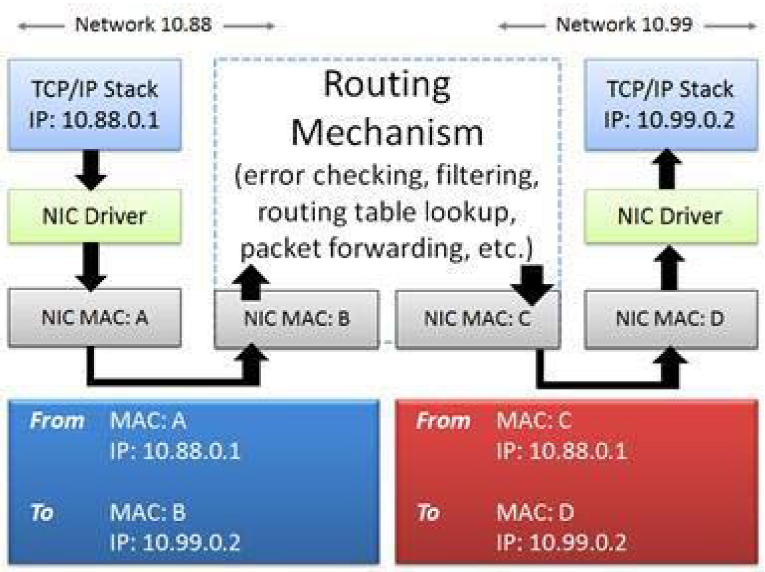
Switches forward packets based on the destination MAC address (also known as the destination hardware address, physical address) contained in the MAC header (like the Ethernet header).

Switches do not change MAC or IP addresses in packets
When a packet reaches a switch, the switch checks the packet to make sure it has the correct checksum. If the packet's checksum is incorrect, the packet is considered bad and the packet is discarded. Switches should keep error counters that show how many packets they throw away due to bad checksums. If the checksum is correct, the switch examines the packet's destination MAC address and consults its MAC address table to determine whether it knows which switch port goes to the host using that MAC address. If the switch does not have the destination MAC address in its tables, it forwards the packet through all the switch ports hoping to discover the responding destination. This process is done with the ARP protocol. If the switch has the destination MAC address in its tables, it forwards the packet to the appropriate port.
Routing
Routers forward packets based on the destination IP address in the IP header. When a packet is sent to the router's MAC address, that router examines the checksum to make sure the packet is valid. If the checksum is invalid, the packet is dropped. If the checksum is valid, the router extracts the MAC header (e.g. Ethernet header) and examines the IP header to determine the "TTL" (Time to Live) and its destination. package. If the packet is too "old" (Time to Live value is 1), the router discards the packet and an ICMP Time to Live Exceeded message is sent back to the sender. If the packet is not stale(TTL time has not been Exceeded), the router looks at the routing tables to determine if the destination IP network is known. If the router is directly connected to the destination network, it can send the packet to the destination. The router reduces the IP header Time to Live value and then creates and applies a new MAC header to the packet before forwarding it
Routers change destination MAC address to destination or next router
If the destination is not on a locally connected network, the router forwards the packet to the next hop router it learned from looking at the routing tables.
Routers may contain rules that block or allow packets based on addressing information. Many routers provide firewall features and can block/allow traffic based on other features.
Proxy, Firewall and NAT/PAT
Firewalls are created to inspect traffic and allow/deny communication based on a set of rules. For example, you may want to block all TCP connection attempts from hosts outside the firewall that are forwarded to port 21 on internal servers.
Basic firewalls operate at Layer 3 of the OSI model, the network layer. In this capacity, the firewall acts as a router when processing network traffic and forwards traffic that is not blocked by firewall rules. The firewall adds a new MAC header to the packet before forwarding it. If the firewall supports additional features such as Network Address Translation (NAT) or proxy capabilities, additional packet switching will occur.
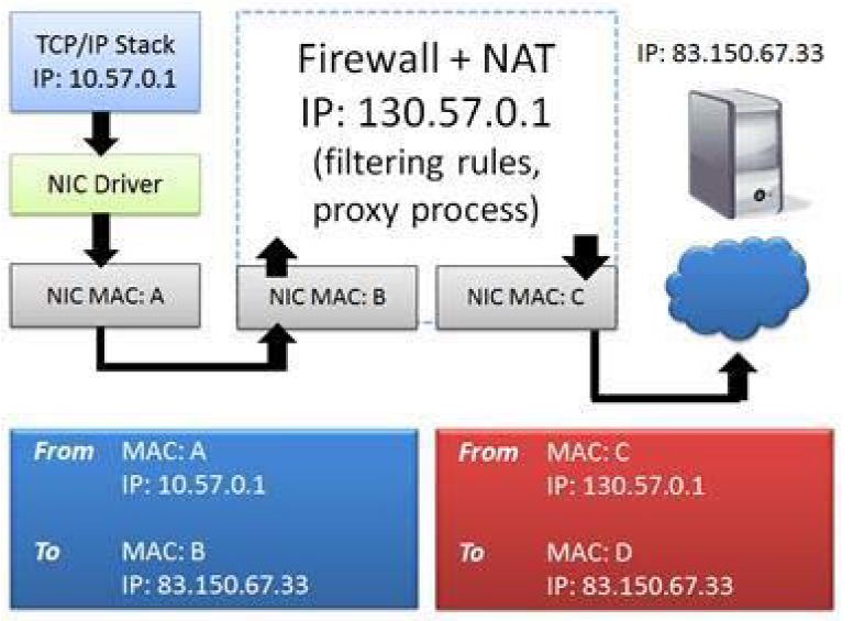
Firewall uses NATÂ to hide the real source IP address
NAT systems change the IP addresses in the packet as shown in Figure. This is often used to hide the client's private IP address. A basic NAT system simply swaps the source and destination IP address of the packet and tracks the connection relationships in a table to properly forward traffic when a response is received.
Port Address Translation (PAT) systems also exchange port information and use this as a method to demultiplex multiple internal connections while using a single outgoing address. The IP addresses you see on one side of a NAT/PAT device are the IP addresses you see on the other side of the NAT/PAT device.will not match. To correlate communications on both sides of a NAT device, you will need to look beyond the IP header to identify matching packets.
Other Technologies
There are many other technologies that affect network traffic patterns and packet contents.
Virtual LAN (VLAN) tagging (defined as 802.1Q) adds an ID (tag) to packets. This tag is used to create virtual networks in a switched environment. Figure 7 shows the VLAN tag in an Ethernet frame. In this case, the sender belongs to VLAN 32.
Multiprotocol Label Switching (MPLS) is a method of creating virtual connections between remote hosts. MPLS packets are prefixed with a special header by MPLS edge devices. For example, a packet sent from a client reaches an MPLS router where the MPLS label is placed on the packet. The packet is now forwarded based on the MPLS tag rather than routing table lookups. The MPLS label is stripped when the packet leaves the MPLS network.
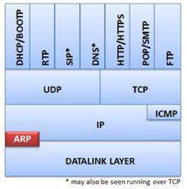
TCP/IP Model
It shows the basic TCP/IP elements along with the TCP/IP Model and the OSI Model. Although the elements of TCP/IP match nicely with the TCP/IP Model, the OSI Model is still constantly referred to in our industry. "Layer 2" devices (switches) and "Layer 3" devices (routers) receive numerical identification according to the OSI Model, not the TCP/IP Model.

TCP/IPÂ elements with the TCP/IP Model and OSI Model
Many network errors or violations can be attributed to TCP/IP protocol or application problems. To recognize these problems we need to know what normal behavior is. Commonly used protocols in the TCP/IP structure are:
- Internet Protocol (IPv4/IPv6) serves as a routable network layer protocol used to receive packets end-to-end across a network. Routers use the information contained in the IP header to make routing decisions. Layer 3 switches can also route traffic.
- User Datagram Protocol (UDP) and Transmission Control Protocol (TCP) provide connectionless and connection-oriented transport layer services, respectively. The port fields in the UDP and TCP headers identify the application used. TCP headers contain fields that also provide sorting and validation services. UDP and TCP are mapped to Layer 4 (Transport Layer) of the OSI Model.
- Routing Information Protocol (RIP) and Open Shortest Path First (OSPF) are two examples of protocols that enable the exchange of network and path information between routing devices.
- Internet Control Message Protocol (ICMP/ICMPv6) is used to provide network information and is commonly recognized as the protocol used for ping. ICMPv6 is used to check and see if an IPv6 address is already in use (duplicate address detection).
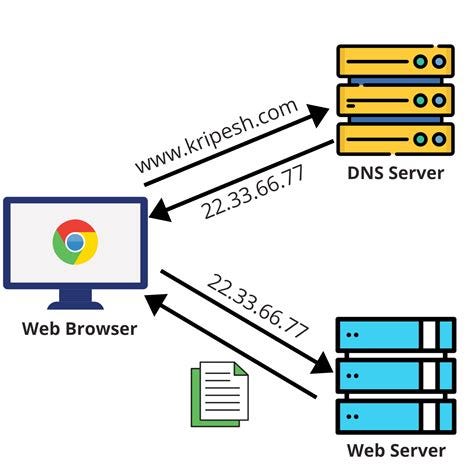
- Domain Name System (DNS) provides hostname-to-IP address resolution services. When you type telnet station3, DNS resolves the station3 name to its IP address. Alias ​​(such as Mail Exchange or MX records) can also be resolved by DNS.
- Dynamic Host Configuration Protocol (DHCP) provides dynamic client configuration and service discovery services, not just IP address information. DHCP can also provide default gateway settings, DNS server settings, and more.
- Address Resolution Protocol (ARP) provides hardware address lookup services for a local device. ARP also allows us to check and see if an IPv4 address is already in use (duplicate address test).
If everything goes well with TCP/IP communication, clients find services quickly. These services respond quickly to requests, and client systems do not need to request a service multiple times. An analyst can uncover large delays between communications, name parsing errors, duplicate requests and retransmissions, insecure practices, and much more. Before analyzing traffic to identify errors, you need to know what is considered normal network communication.
Client â€" FTP Server Scenario
TCP/IP uses a multi-step resolution process when a client communicates with a server. In our example, both the client and server are on the same network. This process includes the following steps:
- Identify the source and destination ports used by the application (port number resolution).
- h if necessaryResolve the edef name to an IP address (network name resolution).
- If the target is on the local network, obtain the target's hardware address (local MAC address resolution).
- If the destination is remote, determine the best router to use to reach the destination (route analysis).
- If the destination is remote, determine the router's MAC address (local MAC address resolution again).
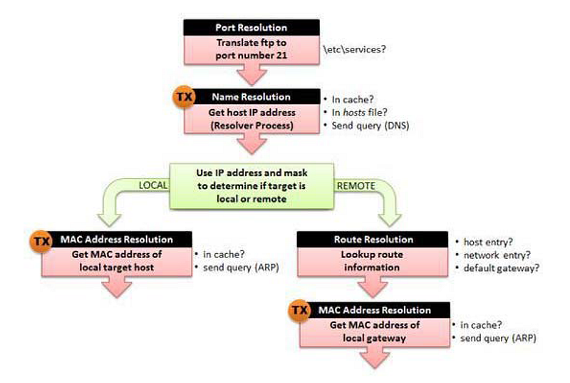
TCP/IP resolution processes
In our example we will consider the connection between a client and the FTP Server.
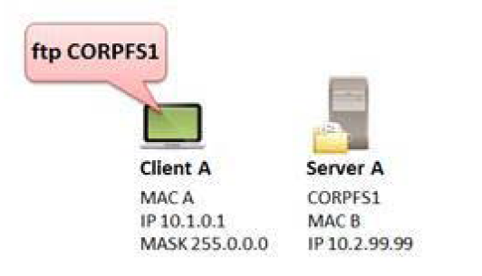
The client wants to make an FTP connection to CORPFS1
Step 1: Port Number Resolution
In our example, the user typed ftp CORPFS1. FTP generally uses port 20 or a dynamic port for data transfer and port 21 for commands such as login and password sending functions, USER and PASS. In our example, the client is trying to connect to the FTP server using port 21. This port number is located in the etc/services file on the client. This number will be placed in the destination port field of the outgoing packet's TCP header. The client uses a dynamic (temporary) port for the source port field value. This process does not create traffic on the network. Therefore, we cannot see any information in the trace file.
Step 2: Network Name Resolution (Optional)
If an explicit destination IP address is defined by the client, network name resolution is not required. If the client has defined a target hostname (CORPFS1 in our example), network name resolution is required to obtain the IP address of the target host.
When performing name resolution, you must follow a certain order:
- Look in the DNS resolver cache for the name.
- If the entry is not in the DNS resolver cache, examine the local hosts file (if available).
- If the local hosts file does not exist or the requested name/address is not in the hosts file, send a request to the DNS server (if one is configured for the local system).
If no response is received from the first DNS server in the configured DNS server list, the client can try to redirect the query to the first DNS server or query the next known DNS server. Still no answer? Are there no other known DNS servers? If the client cannot resolve the value to be placed in the destination IP address field, it cannot create the packet.
In our example, we can see that the client sends a DNS query to the first DNS server listed in its local configuration. (If all goes well) we should see a response from a DNS server containing the IP address of CORPFS1.
This process can generate traffic on the network, as shown by TX in Figure 181. If name resolution uses the local hosts file or retrieves the requested information from the cache, no packets are sent. If a DNS query needs to be sent, it will appear in the trace file.
Step 3: Route Analysis-When Destination is Local
During this process, the client determines whether the target device is local (on the same network) or remote (on the other side of a router). The client compares its network address with the target network address to determine whether a target is on the same network. In the example shown in Figure 180, the client's IP address is 10.1.0.1/8 (network 10). The IP address of the server is 10.2.99.99. The target is also on network 10.
Consider possible consequences depending on the client's IP address and subnet mask.
- Source address 10.1.22.4 with subnet mask 255.0.0.0 = CORPFS1 is local (go to step 4)
- Source address 10.1.22.4 with subnet mask 255.255.0.0 = CORPFS1 is remote (go to step 5)
- Source address 10.2.22.4 with subnet mask 255.255.0.0 = CORPFS1 is local (go to step 4)
This process does not generate traffic on the network.
Step 4: Local MAC Address Resolution
If the target device is local, the client must resolve the MAC address of the local target. The client first checks the ARP cache for this information. If this information is not available, the client sends an ARP broadcast to find the hardware address of the target. When an ARP response is received, the client updates the ARP cache.
This process may generate traffic on the network as indicated by TX. If the MAC address is cached, no packets will be sent. If an ARP query needs to be sent, it will appear in the query trace file.
Step 5: Route Analysis-When the Destination is Far
If the target device is remote, the client must perform route analysis to determine the appropriate nexthop router.takes it. The client looks at local routing tables to determine if a host or network route entry exists for the destination. If there is no entry, the client checks for a default gateway entry. This process does not create traffic on the network.
The Default Gateway provides a "blind faith" path â€" since the client has no route to the destination, it sends the packet to the default gateway and hopes the default gateway can figure out what to do with the packet.
Default gateways usually either forward the packet (if they have the best route to the destination), send an ICMP redirect response pointing to another local router with the best route to the destination, or return a response indicating that they have no idea where to send the packet (ICMP Destination Unreachable).
Step 6: Local MAC Address Resolution for a Gateway
Finally, the client must resolve the MAC address of the next hop router or default gateway. The client first checks the ARP cache. If the information is not in the cache, the client sends an ARP broadcast to retrieve the information.
Next updates the router's MAC address and ARP cache.
This process may generate traffic on the network as indicated by TX. If a requested router's MAC address is cached, no packets will be sent. If an ARP query needs to be sent to the requested router, this query will appear in the trace file.
Package Analysis
If all goes well (and in this case the target is local), we should have resolved the following information during this process:
- Destination MAC address
- Destination IP address
- Source and destination port numbers
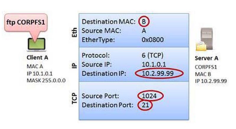
Discovered information for TCP/IP packet over Ethernet
TCP/IP Traffic Analysis
In this section, we will examine the http-riverbed-one.pcapng and http-riverbed-two.pcapng files. You can access it from the bibliography section.
These two files belong to a client that accessed www.riverbed.com 89 seconds apart.
In the http-riverbed-one.pcapng file, we naturally see that there are DNS queries first. In order to create packets, the client must resolve the domain and obtain destination IP information.

DNS queries for domain resolution in the http-riverbed-one.pcapng file
We notice that there are no initial DNS queries to the http-riverbed-two.pcapng file. This indicates that the client has some of the requested IP addresses in its DNS cache, so there is no need to create a DNS query for these names.

DNS queries do not appear in the http-riverbed-two.pcapng file.
Most of the DNS responses in the http-riverbed-one.pcapng file cached the client's name resolution information for a short period of time and did not resubmit the DNS query.
However, if the session time is exceeded, we can see in the http-riverbed-two.pcapng file that our browser sends DNS queries to re-resolve these names.

Revamped DNS resolutions in http-riverbed-two.pcapng
You will also notice that the total number of packages in http-riverbed-two.pcapng is only 319. In addition to fetching some of the DNS information from the cache, the browser also displayed a large number of page elements from the cache.
When we look at the protocol statistics (Statistic | Protocol hierarchy) in the http-riverbed-one.pcapng file, we see that most of the traffic uses TCP. Because the HTTP protocol uses TCP. When we look at UDP traffic, we see that it uses the Domain Name System (DNS) protocol.

http-riverbed-one.pcapng Protocol Statistics
To see the dominant traffic in http-riverbed-one.pcapng file Statistic| We can open the Conversations window. If we sort by packets when we open the IPv4 tab here, we can say that the dominant traffic is between IPs 24.61.173.220 and 208.70.196.59 with 1140 packets going between hosts.
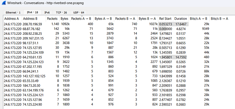
conversations
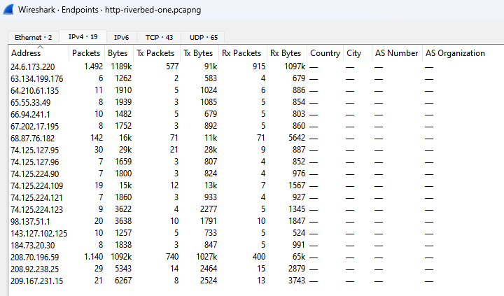
Statistic| in http-riverbed-one.pcapng IP name mentioned in traffic in the Endpoints windowWe can see the pictures. All of the IP addresses here seem to be public IP addresses. Therefore, we can say that the traffic was captured on an external network.
endpoints
Statistic| in http-riverbed-one.pcapng HTTP| In the Requests window, we can view the web addresses visited in the pcap file.
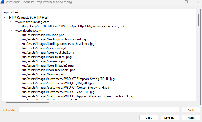
Requests
In http-riverbed-one.pcapngÂ
ip.addr == 24.6.173.220 && ip.addr == 208.70.196.59Â
Let's examine the dominant traffic we found before by typing its filter.

Dominant Traffic
If we click on the HTTP packet and select the follow HTTP Stream option, we can view all HTTP traffic.

Follow HTTP Stream
We are faced with a long flow. Here he found the traffic to and from www.riverbed.com. We can see the HTTP connections established with this address as request (red text) and response (blue text).
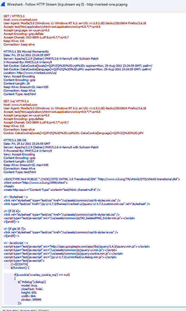
www.riverbed.com HTTP Stream
References
- Wireshark Network Analysis, Second Edition, Laura Chappell, https://www.chappell-university.com/studyguide
- Trace Files: https://s3.amazonaws.com/book.supplements/StudyGuide_v2/9781893939943_traces-set1b.zip
DNS Wireshark Analysis
Hello, in this article, I will try to explain the Domain Name System (DNS) protocol and its analysis with Wireshark.
How Does DNSÂ Work?
DNS is used to convert symbolic hostnames, such as www.wiresharktraining.com, into IP addresses. DNS can also be used to transfer name information between DNS servers, determine the hostname associated with an IP address (reverse or pointer query), and look up other name elements such as an MX (mail exchange) record.
DNS is one of the most important applications on the network. A DNS problem will prevent computers from finding each other when using hostname information.

DNS package
DNS can operate over UDP or TCP. You'll commonly see DNS queries and responses that use UDP. Zone transfers operate over TCP. The default port number for DNS is 53.
RFC 1035, Domain Names â€" Implementation and Specification limits DNS over UDP packet payload to 512 bytes. This is usually enough for a DNS query. However, when a response requires more than 512 bytes of space, an interrupt flag bit is sent in the response. This triggers the resolver to resend the DNS query using TCP, which allows for a larger packet size.
RFC 2671, Extension Mechanisms for DNS (EDNS0), allows more than 512 bytes over UDP.
DNS Query/Response Analysis
Domain resolution, DNS query and response operations are very simple. A client sends a DNS query to a DNS server, requesting an IP address, usually in exchange for a domain. The DNS server either responds directly with the information it has or asks other DNS servers on behalf of clients.

A record DNSÂ Query
The figure shows a standard DNS request to the A record (CNAME) for www.winpcap.org. This DNS query is automatically generated when the user enters the domain in the browser URL and presses the Enter key.
The name requested by a client may not be the real name of the target. In this case, a canonical name(CNAME) or real name is returned for www.winpcap.org. The CNAME is winpcap.org and the address of this host is 128.121.79.138.
DNS Errors Analysis
The most common DNS problem is an error that occurs because a name does not exist in the ad namse server database. This may be due to entering an incorrect name or entering a new name that has not yet been propagated to Internet name servers.

Unfound Domain Query
In the figure, a user is trying to access the address 2.26.64.24.in-addr.arpa. The Name Server responds by stating that there is no such domain. If the user cannot resolve the domain, he cannot reach the destination address.
Server error responses indicate that the name server was unable to resolve information for the client due to an error. This could be because the name server sent a query to another name server (via a recursive query) and timed out waiting for a response, or it could be that the response was not understood or related to a query due to some kind of internal error.

IP Resolution Cannot Be Performed as a Result of DNS Errors
The figure shows the server error response received when trying to reach www.nmap.org. We know this is a valid address, but DNS cannot resolve it. We cannot reach the site due to a DNS problem. Pay attention to the time column; We can see that the client sends a DNS query, then waits 1 second for the response before resending the query. The client waited another 1 second before the third query, but doubled that wait time to approximately 2 seconds before the fourth DNS query.
To find the cause of DNS problems, you may need to move Wireshark upstream of the DNS server and monitor the lookup process at that location.

The ICMP response indicates that port 53 is open on the target.
In the figure, our client sends DNS queries and these queries are answered with ICMP Destination Unreachable/Port Unreachable responses.The response shows that port 53 is not open on this host.
In this case, where the error occurs depends on whether the client's DNS server has the correct IP address or whether the DNS server service is running on the requested IP. In this case, the client tries again â€" there is only one DNS server configured (usually there will be 2), so it tries the lookup again. The client's request is rejected again because the server indicates that this port is not listening.
DNS Package Structure
Unlike other applications that use a single transport protocol (UDP or TCP), DNS uses both UDP and TCP. DNS generally uses UDP-53 for name resolution requests and responses, and TCP-53 for zone transfers and larger name resolutions and responses.
DNS name reqests to www.winpcap.com
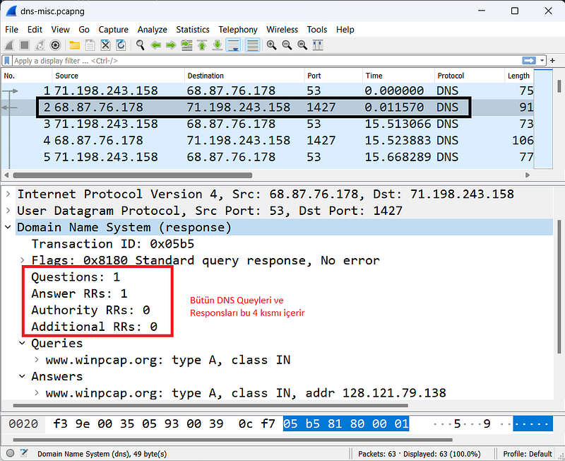
All DNS packages use a single basic structure consisting of four main parts as shown in the Figure.
Transaction ID
The Transaction ID field associates DNS queries with responses. You can filter on this field and value (for example, dns.id==0x05b5) to view all associated DNS queries/responses.
####Flags
The flags byte consists of multiple fields that define query properties.
Query/Response
The Query/Response bit indicates whether the packet is a query (0) or a response (1). You can create a Wireshark filter to view DNS queries (dns.flags.response==0) or responses (dns.flags.response==1).
Opcode
The Opcode field specifies the query type. Most commonly, this field contains 0000 for standard queries, and the field is left as 0000 in responses.
Authoritative Answer
The Authorized Response field used in responses indicates that the response comes from an authoritative server for the domain.
Truncation
A truncation area indicates that the DNS response was truncated due to length. If a client sees a truncated DNS response, it must retry the query over TCP. It's not very common to see TCP based queries/responses.
Recursion Desired
Recursion can be defined in DNS queries to specify whether the server can use recursive query operations. Recursion allows a DNS server to request a response from another server on behalf of the client. If the local nameserver has the answer, it will respond directly. If it doesn't have the answer, it will begin the search on behalf of the client.
Recursion Available
This setting, described in the answers, specifies whether recursion is available on the DNS server.
Reserved
This field is set to 0.
Rcode (Response Code)
The rcode field indicates whether there is an error condition in the response. The table below lists possible Rcode values.
- Code 0: No error condition.
- Code 1: Format error - query could not be interpreted.
- Code 2: Server error - the server was unable to process the query due to a problem with the nameserver.
- Code 3: Name error - domain does not exist.
- Code 4: Not implemented.
- Code 5: Denied - the nameserver refuses to perform the function due to policy.
Question Count
This field shows the number of questions in the Question section. You'll typically see only one question per query package.
Answer Resource Record (RR)Â Count
This field shows the number of responses in the Response RRs section. If a response contains CNAME information, you will likely see two numbers in the Response RR Number field â€" one for the CNAME and one for the IP address of the CNAME record.
Authority RRs Count
This field shows the number of responses in the Authority RRs section. These responses come from servers that are closer to the target name in the naming hierarchy.
Additional RRs Count
This field shows the number of responses in the Additional RRs section. In this section you can find A records for servers in the Authority RR section.
Queries
This variable-length field identifies the name being parsed and the type of information requested.
Name
This field contains the name being resolved. The format is variable length, using a numeric delimiter to specify the number of alphanumeric bytes in the name. Below are some examples:
*3www9wireshark3org0
*3www4iana3org0
####Type
This field shows the query type. For a complete list of registered type numbers, see www.iana.org/assignments/dns-parameters.
- Type A: Host address
- Type NS: Authoritative name server
- Type CNAME: Canonical name for an alias
- Type SOA: Start of Zone Authority
- Type PTR: Pointer record
- Type HINFO: Host information
- Type MX: Mail exchange
- Type AAAA: IPv6 address
Class
This field is set to 1 to specify an Internet class address for TCP/IP communications.
Answer RRs
This area uses the same format as this section in the Questions area.
Authority RRs
This area uses the same format as this section in the Questions area.
Additional RRs
This area uses the same format as this section in the Questions area.
Resource Record Time to Live (TTL)Â Value
This field is located in the Response section of DNS responses and indicates how long the recipient can cache DNS information. Each response in DNS will contain a TTL value for that DNS information.
DNS servers responding with RR information continuously count down the remaining TTL value; Making the same DNS query ten seconds apart will show a ten second difference in the TTL value presented.
DNS/mDNS Traffic Filters
The capture filter for DNS traffic is based on the port number because the tcpdump filter format cannot detect the dns protocol. This may change as Libpcap and WinPcap are updated.
The capture filter for standard DNS traffic over UDP or TCP is port 53, while mDNS uses port 5353.
The view filter syntax is simply dns. This filter displays both DNS and mDNS traffic. Additional DNS display filters are listed below.
- dns.flags.response==0: DNS query
- dns.flags.response==1: DNs response
- dns.flags.rcode != 0 : DNS responses containing errors
- dns.count.answers > 5: DNS responses containing more than 5 responses
- dns.qry.name=="www.abc.com"Â : DNS query for www.abc.com
- dns contains "abc": DNS query or responses "containing abc"
- dns.qry.type==0x0001: DNS queries for a hostname.
- dns.qry.type==0x000c: DNS queries for a domain pointer query(inverse query).
- dns.resp.type==0x0005: DNS responses containing CNAME value (canonical name)
- dns.resp.type==0x0006: DNS responses containing SOA (Start of Authority)
- dns.flags.recdesired==1: DNS Queries with recursion desired
- dns.flags.recavail==1: DNS responses starting with recursion available
More Display filter options can be found in Wireshark's Reference at www.wireshark.org/docs/dfref/d/dns.html.
References
- Wireshark Network Analysis, Second Edition, Laura Chappell, https://www.chappell-university.com/studyguide
- Trace Files: https://s3.amazonaws.com/book.supplements/StudyGuide_v2/9781893939943_traces-set1b.zip
ARP Wireshark Analysis
Hello, in this article, I will try to explain the Address Resolution Protocol (ARP) protocol and its analysis with Wireshark.
How Does ARPÂ Work?
ARP is used to associate a hardware address (physical address, MAC address) with an IP address on the local network and to test for duplicate IPv4 addresses. No matter how simple ARP is, it can be the protocol that signals problems with network addressing or configurations. ARP is defined in RFC 826, Ethernet Address Resolution Protocol, and is not used in IPv6 communications.
ARP Protocol
**ARP protocol can only be used on the local network (internal network)!**Therefore, to analyze ARP conversations, you must be connected to the local network where the traffic flows.
Provides address resolution between ARP, MAC and IP address layers
ARP packets are unique compared to most traffic on a TCP network because they do not contain an IP header (it is not a protocol operating at the Internet layer). This feature means that ARP packets are packets that cannot be routed (since it is a data-link layer protocol).
ARP Requests/Responses Analysis
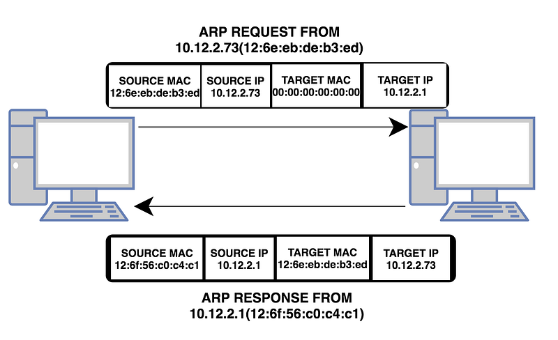
Normal ARP communications consist of a simple request and a simple response. A host sends an ARP broadcast containing the destination IP address (but no destination MAC address â€" ARP is used for MAC address resolution).

ARP request
In the figure, a host with a MAC address of 00:23:54:69:8f:58 and an IP address of 24.6.170.101 is looking for the MAC address for 24.6.168.1. In broadcast broadcasts, the MAC address is 00:00:00:00:00:00 as shown in the figure. This is because switches forward packets according to the destination MAC address in unicast traffic. MAC address with 0 represents broadcast transmission.
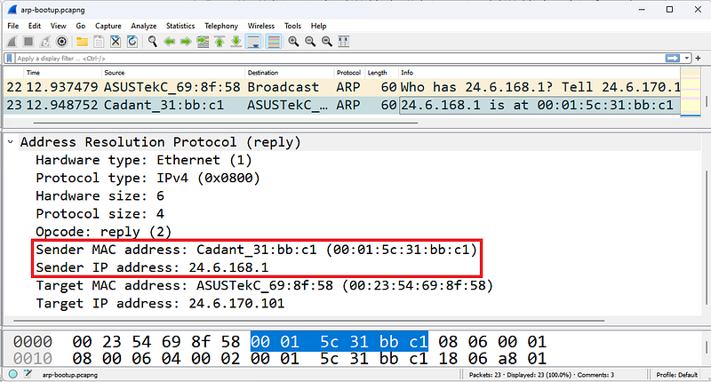
ARP Response
The response packet shown in the figure now contains the sender IP address 24.6.168.1 and the MAC address of this device. The sender and destination addresses are associated with the current packet sender in ARP requests and responses. So the response returns as unicast.
Analysis of ARP Problems
Missed ARP requests are used to determine whether another host on the network has the same IP address as the sender. It sends ARP requests to all hosts regardless of whether their IP addresses are statically or dynamically assigned. If there is no response, it is determined that this IP address is not used on the network and is empty. Wireshark can identify missed ARP packets.

ARP Announcement
In the figure, a host checks whether another device on the network is using the IP address 24.6.170.101.
If you are examining ARP traffic but seeing no response to ARP broadcastsÂ
(a) may not be connected to a location where you can see unicast replies â€" orÂ
(b) The ARP broadcast is a missed ARP and no response indicates an IP address conflict.
Misconfigurations
Network addressing issues can also cause ARP problems.

An ARPÂ issue caused by a misconfigured host subnet value
In the figure, Client A is configured with the wrong subnet mask. When Client A goes through the resolution process to determine whether the target Server A at address 10.2.99.99 is local or remote, Client A determines that the server is local. Client A believes the server is on the 10.0.0.0/8 network. Client A believes that the server is also located on the 10.0.0.0/8 network. This is because Client A's subnet mask is set to 255.0.0.0.
Proxy ARP
Routers that support proxy ARP (defined in RFC 1027, Using ARP to Implement Transparent Subnet Gateways) can respond on behalf of devices on other networks. There are numerous disadvantages to using proxy ARP, including an increase in overall ARP traffic.
ARP Poisoning
ARP poisoning traffic also appears uniquely on Wireshark.

Harp Poisoning
In the figure, Wireshark has detected that duplicate addresses are being used. A host at address 00:d0:59:aa:af:80 has both 19We can see that it is sending arp responses to both 2.168.1.103 and 192.168.1.1. This is the first phase of an ARP-based MITM(Man-in-the-Middle) attack.
ARP Packet Structure
There are two basic ARP packets: ARP request packet and ARP response packet. Both packages use the same format. The most confusing part of ARP is the interpretation of sender and destination address information. When an ARP broadcast is sent from a host, the sending host puts the hardware and IP addresses in the sender address fields.
The target protocol address field contains the IP address of the called device. The target hardware address field is set to all 0s to indicate that the information is unknown. In an ARP response, the destination and sender information are reversed to indicate that the ARP responder is now the sender. The original station that placed the call is now the target.
Hardware Type
This identifies the type of hardware or data connection used. Hardware type 1 is assigned to Ethernet and defines a hardware address length of 6 bytes. The complete Hardware Type field value list is available at www.iana.org.
Protocol Type
This field defines the protocol address type used. This field uses standard protocol ID values ​​that are also used in Ethernet II frame structures. These protocol types are defined at www.iana.org/assignments/protocol-numbers.
Length of Hardware Address
This field defines the length (in bytes) of the hardware addresses used in this packet.
Length of Protocol Address
This field defines the length (in bytes) of the protocol (network) addresses used in this packet.
Opcode
The opcode identifies whether the packet is a request or response packet and the type of address resolution that occurs.
Listed below are the ARP and RARP (reverse ARP) opcodes:
- Opcode 1: ARP request
- Opcode 2: ARP reply
- Opcode 3: RARP request
- Opcode 4: RARP reply
A process that allows a device to learn its network address from a MAC address. RARP is defined in RFC 903, A Reverse Address Resolution Protocol. We do not see RARP being used except in very old network environments where RARP was used as an early address assignment protocol.
Sender's Hardware Address
This field shows the hardware address of the device sending this request or response.
Sender's Protocol Address
This field shows the protocol (network) address of the device sending this request or response.
Target Hardware Address
This field indicates the desired target hardware address, if known. In ARP requests this field is usually filled with all 0's. In ARP responses, this field contains the hardware address of the device sending the ARP request.
Target Protocol Address
This field indicates the destination protocol (network) address requested in a request. The response includes the address of the device that issued the request.
Filtering ARP Traffic
For ARP traffic, the capture filter and display filter are simply arp. Additional ARP display filters are listed below:
- arp.opcode==0x0001 â€" ARP request
- arp.opcode==0x0002 â€" ARP reply
- arp.src.hw_mac==00:13:46:cc:a3:ea â€" ARP source physical address 00:13:46:cc:a3:ea (request or response)
- (arp.src.hw_mac==00:21:97:40:74:d2) && (arp.opcode==0x0001) â€" ARP request with source physical address 00:21:97:40:74:d2
- (arp.src.hw_mac==00:d0:59:aa:af:80) &&Â !(arp.src.proto_ipv4==192.168.1.1)
In the ARP packet, a host at the address 00:d0:59:aa:af:80 sends ARP reply packets (arp poisoning) to external IP addresses from its own IP address (192.168.1.1). - (arp.opcode==0x0002) && !(arp.src.proto_ipv4==192.168.0.1/16) â€" ARP packet (ARP proxy response)-proxy ARP where the resolved IP address is for the remote device.
References
- Wireshark Network Analysis, Second Edition, Laura Chappell, https://www.chappell-university.com/studyguide
- Trace Files: https://s3.amazonaws.com/book.supplements/StudyGuide_v2/9781893939943_traces-set1b.zip
IPv4/IPv6 Wireshark Analysis
Hello, in this article, I will try to explain the IPv4 and IPv6 protocols and their analysis with Wireshark.
What is IP?
IP (v4/v6 â€" collectively referred to as "IP") provides delivery services for networked systems as well as fragmentation and reassembly for low MTU (Maximum Transmission Unit) networks. IP also offers quality of service determination to ensure that certain traffic is prioritized over other traffic.
IP is connectionless and unreliable, providing optimal delivery of datagrams between IP hosts. IP itself provides no way to determine whether a packet has reached its destination. An application that needs guaranteed delivery should use TCP over IP.

Provides delivery services for IP, UDP and TCP based applications and ICMP
The IPv4 header is typically 20 bytes long, but contains a field that can extend the IP header length (in 4-byte increments).
IPv4 Analysis
IPv4 is covered in RFC 791. Normal IPv4 communication moves packets from one location to another using the most efficient packet size.
As IPv4 packets are forwarded by routers, the destination IP address is examined to make routing decisions, the MTU size is checked against the MTU size of the next connection (to determine whether fragmentation is required and allowed), the MAC header is removed and a new one is applied for the next network, and the time-to-live (TL) value in the IP header is reduced. The IP header is also checked for routing prioritization.
If all goes well in an IPv4 communication, traffic should flow to and from IP addresses. The IPv4 address in the header should not change unless a NAT/PAT device intercepts traffic and changes the address.
If a packet is too large to be forwarded to the next link in the path, the router examines the IP header fragmentation setting. If the Don't Fragment bit is set, the packet cannot be transmitted. The router must send an ICMP Type 3, Code 4 message (Destination Unreachable/Fragmentation Required, but Fragmentation Bit Set) to the originator of the packet, identifying the MTU limitation. The sender must retransmit the packet in a smaller packet size. If fragmentation is allowed, the router must split the single large packet into two (or more) smaller packets, define the fragment offset, and indicate that the packets are fragments and forward them.
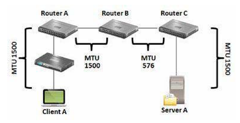
IP can fragment packets when a connection's MTU does not support the datagram size
In the figure, a 1500 byte MTU packet from Client A to Server A cannot travel along the path. The limitation is in the connection between Router B and Router C. Router B must split the packet into fragments (if allowed) and forward the fragments or send the ICMP Type 3, Code 4 message back to Client A.
Fragmentation is not desirable in a network because it reduces the efficiency of data flow. However, it may be inevitable. To identify possible MTU problems in wirehsark;
Statistics | Examine Packet Lengths or apply a filter for ICMP Type 3/Code 4 packets (icmp.type==3 && icmp.code==4).
IPv4 problems are often related to fragmentation, unusual IP addresses, and excessive broadcasts. A few examples are given below.
- Fragmentation problems can occur when ICMP Type 3, Code 4 packets are blocked, preventing a host from learning why its packets did not reach the destination. ICMP Type 3, Code 4 packet is used for black hole detection.

Source IP address 127.0.0.1 is suspicious
- Unusual IP addresses may be duplicate addresses or addresses that are not allowed on the network, such as the address shown in the Figure. The IP source address cannot be a loopback address (127.0.0.0/8), a multicast address, or a broadcast address.
- Excessive broadcasts flowing across a network can be easily detected by connecting Wireshark to a switch.
The figure shows a packet that should never be on the network â€" the source is the loopback address 127.0.0.1.
IPv6 Analysis
IPv6 is a layer 3 routed protocol only.

IPv6 Header
The figure shows an IPv6 headeris. Notice that the Ethernet header Type field is 0x86dd, which indicates that an IPv6 header is in order.
RFC 2460, Internet Protocol, Version 6 (IPv6) Specification, defines the IPv6 header specification. IPv6 addressing is covered in RFC 4291, IP Version 6 Addressing Architecture. For details on how IPv6 hosts discover other local targets, see RFC 4861, Neighbor Discovery for IP version 6 (IPv6).
This short section on IPv6 is just intended to give you a look at the most common IPv6 traffic you'll see on dual-stack hosts.
There are three different types of addresses in IPv6 communications:
- Unicast â€" single interface address
- Multicastâ€"set of interfaces
- Anycast â€" the closest of a group of interfaces
There is no broadcast address in IPv6 - multicasts are used instead of network broadcasts.
IPv6 addresses are sixteen bytes long (128 bits) and are written as x:x:x:x:x:x:x; where x represents one to four hexadecimal digits. You can omit leading zeros in a single field to shorten the notation.
Multicast broadcasts start with ff02
RFC 4291 provides the following example for IPv6 addresses:
- Address 2001:0DB8:0:0:8:800:200C:417A (a unicast address)
Shortened Version 2001:DB8::8:800:200C:417A - Address FF01:0:0:0:0:0:0:101 (a multicast address)
Shortened Version FF01::101 - Address 0:0:0:0:0:0:0:1 (a loopback address)
Shortened Version ::1 - Address 0:0:0:0:0:0:0:0 (unspecified address)
Shortened Version ::
:: can be used only once in an address and represents one or more groups of 16-bit zeros. :: can also be used to represent leading or trailing zeros in an address. Wireshark uses the shortened version of IPv6 addresses as shown in the figure above.
Classless Inter-Domain Routing (CIDR) notation is used when representing IPv6 network prefixes. For example, 2001:DB8:0:CD30::/64 represents the 2001:DB8:0000:CD30:: network.
Unicast addresses start with 2xxx. Multicast addresses start with FFxx. Link-Local Unicast addresses start with FE80.
Link-Local addresses are used for addressing on a single link and are not routed. IPv6 uses Link-Local addresses for automatic address configuration and neighbor discovery.
The first packet seen in the figure above is an ICMPv6 Request â€" this protocol replaces ARP. When the source address is ::, the purpose of the packet is Duplicate Address Detection (DAD).
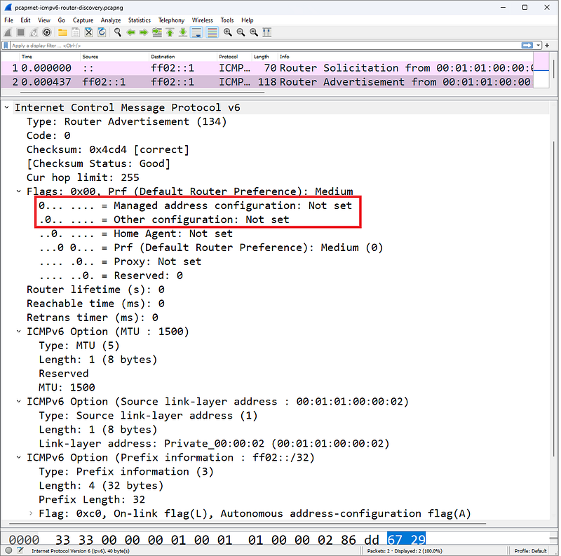
Managed Address Configuration and Other Configuration bits define how a DHCPv6 client receives an IPv6 address and other parameters
An IPv6 host can obtain an address using one of several methods defined by the Router Advertisement packet sent to the IPv6 host during the startup process. We noted two bits in the figure:
- Managed Address Configuration (M) bit
- Other Configuration (O) bit.
DHCPv6 client address and other parameters will be configured according to the setting of these two bits. An IPv6 client can obtain an address in three different ways by referencing the M and O bits in the ICMPv6 Router packet:
- Stateless Address AutoConfiguration (SLAAC)
- stateful DHCPv6
- stateless DHCPv6
6to4 Tunneling(IPv6 Tunneled Within IPv4)
As part of the transition to IPv6, existing TCP/IP hosts support dual stacks and IPv6 tunneling capability within IPv4. These packets can be routed to the destination IPv6 host over an IPv4 network. There are three different encapsulation methods - 6to4, Teredo and ISATAP.

Protocol value 41 indicates an IPv6 header comes later
RFC 3056, Connecting IPv6 Domains over IPv4 Clouds, defines 6to4 tunneling. When Wireshark detects that an IPv6 header follows an IPv4 header, it adds two notes to the packet:
- Source 6to4 Gateway IPv4 (ipv6.src_6to4_gw_ipv4)
- Source 6to4 SLA ID (ipv6.src_6to4_sla_id)
The first 2 bytes of the source address will be 0x2002. The 6to4 Gateway address is the IPv4 address of the encapsulating host (either a client that embeds the IPv6 header or a router that embeds the IPv6 header). In Figure 209, the source IPv6 address contains 0x1806addc, which translates to 24.6.173.220 (the IPv4 address of the host). The resource 6to4 SLA Identifier (Site Level Aggregation Identifier) ​​is used to identify a subnet.
Teredo
Teredo, oneIt is another tunneling method that encapsulates the IPv6 header within a UDP packet. This technology was developed to help bypass Network Address Translation (NAT) devices that do not handle Protocol 41. Teredo is covered in RFC 4380, IPv6 Tunneling over UDP via Network Address Translations (NATs).
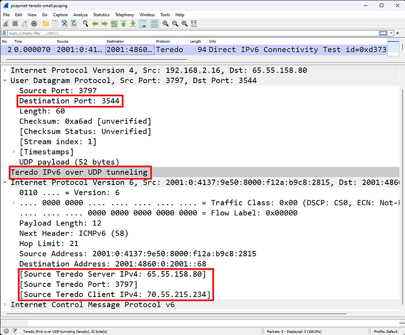
Teredo tunnels IPv6Â inside a UDP packet
The figure shows a packet going from a Teredo client to a Teredo server. Wireshark uses Teredo port udp-3544 and provides Teredo IPv6 over UDP tunneling dissector.
Here we can see three Wireshark notations:
- Source Teredo Server IPv4 (ipv6.src_ts_ipv4)
- Source Teredo Port (ipv6.src_tc_port)
- Source Teredo Client IPv4 (ipv6.src_tc_ipv4)
Intra-Site Automated Tunnel Addressing Protocol (ISATAP)
Both 6to4 and ISATAP encapsulate IPv6 within IPv4, but the packet is sent differently over an IPv4 network. Wireshark can detect that ISATAP is in use (just like Teredo detects that it is in use).
Unlike 6to4 tunneling, ISATAP uses a locally assigned IPv4 address (public or private) to generate a 64-bit interface identifier. For example, in ISATAP the IPv4 address 24.6.173.220 would be::0:5EFE:1806:addc. In a 6to4 tunnel configuration, the same IPv4 address would be 2002:1806:addc::/48, as seen in Figure 210.
ISATAP requires ISATAP routers to configure an intrasite tunnel for IPv6 traffic and is covered in informational RFC 5214.
IPv4 Packet Structure
In this section, header fields and their functions are explained in detail. You can see RFC 791 for more details on each field.

IPv4 Header
The figure shows a standard IPv4 header with acceptable IPv4 addressing.
Version Field
The first field in the IP header is the version field. The figure shows a fully extended IPv4 header. In this section we will start with IPv4 and then examine IPv6.
Header Length Field
This field is also called the Internet Header Length field or IHL(Internet Header Length). This field simply specifies the length of the IP header. This field is required because IP supports different header lengths. This field value is provided in multiples of 4 bytes. For example, the actual decimal code for this field will be 5. Wireshark multiplies this value by 4 bytes to get the actual IP header length value of 20 bytes. In the figure, the IPv4 header is 20 bytes long. No different header length is used in this IP header.
Differentiated Services Field and Explicit Congestion Notification
The six-bit Differentiated Services Domain (DiffServ) is used to prioritize traffic and provide a certain level of Quality of Service (QoS).
The field contains a Differentiated Services Code Point (DSCP) value that is used to determine how the packet will be processed (per-hop behavior).
Assured Forwarding and Expedited Forwarding Per-Hop Behavior
RFC 2597, Assured Forwarding The PHB Group defines Assured Forwarding as a means for a DiffServ provider to offer different levels of forwarding assurances for IP packets it receives from a DiffServ customer.
RFC 2598, an Accelerated Routing PHB, defines that Accelerated Routing "can be used to create a low-loss, low-latency, low-jitter, guaranteed bandwidth, end-to-end service via DS (DiffServ) domains. Such a service appears as a point-to-point connection or 'virtual leased line' to endpoints. This service is also described as a Premium service."
The two-bit Explicit Congestion Notification (ECN) field is used by the sender and/or routers along the path to identify network congestion along the path.
Total Length Field
This field defines the length of the IP header and valid data (this does not include any data connection padding).
In the example shown in the figure, the total length field value is 1500 bytes. The first 20 bytes of this are the IP header â€" this indicates that the remaining packet length (not including any data link padding) is 1480 bytes.
Identification Field
Each IP packet is given a unique ID value when sent. If the packet needs to be fragmented to fit on a network that supports a smaller packet size, these fragments will be the same.The same identification number will be placed on each piece to identify it as part of the original package.
Flags Field
The flags field is actually three bits long and has the following bit value assignments:
- Bit 0: Set to reserved-0.
- Bit 1: Shred Bit (0=can shred; 1=does not shred)
- Bit 2: More Track Bit (0=last track; 1=more to come)
An application (application layer protocols) can be written in a way that does not allow fragmentation. If so, the application will set the Don't Fragment bit to 1. If fragmentation is allowed and a packet must be fragmented to traverse a network that supports a smaller packet, the MTU will set the Fragmentation bit to 0. When the packet is split into multiple fragments -three For example, the More Fragments to Come bit will be set to 1 on the first and second fragments. The More Fragments bit of the last fragment is set to 0, indicating that it is the last fragment in the set. All fragments will use the same IP ID value. Fragmentation and recombination occur at the extreme.
Fragment Offset Field
If the packet is a fragment, this field indicates where the data for this packet will be placed when the fragments are combined back into a single packet (on the target host). This field provides the offset in 8-byte values. For example, the first fragment might have an offset of 0 and contain 1400 bytes of data (not including any headers). The offset value of the second piece will be 175 (175 x 8 = 1400). This field is used only if the packet is a fragment, otherwise it is set to 0.

Wireshark viewing IP fragments
Time to Live Field
This field shows the remaining lifetime of the packet (in seconds and number of hops through routers).
Typical initial TTL values ​​are 32, 60, 64 and 128. Default TTL values ​​are included in the vendor's TCP/IP stack. Applications (such as traceroute) can override these default values ​​as desired. Each time a packet is transmitted by the router, the router must decrement the TTL field by 1. If the router needs to keep the packet in its queue for a long time (more than one second), it should reduce this TTL value by the number of seconds the packet is held in the queue and reduce the TTL for the hop.
If a packet to be forwarded reaches a router with TTL=1, the router must discard the packet because it cannot reduce the TTL to 0 and cannot forward the packet. The router can indicate to the sender that the packet was not delivered due to the Time to Live value by generating an ICMP Type 11, Code 0 response (Time Exceeded, Time to Live Exceeded in Transit).
If a packet with TTL=1 reaches a host, what should the host do? Of course it processes the package. Hosts do not need to lower the TTL value after receiving or forwarding packets.
Because low TTL values ​​are sometimes considered unusual, Wireshark has a coloring rule called TTL low or unexpected that helps identify these packets in a trace file. Coloring rule syntax (!ip.dst==224.0.0.0/4 && ip.ttl < 5 && !pim) || (ip.dst==224.0.0.0/24 && ip.ttl != 1).
When a packet is fragmented, all fragments are given the same TTL value. If they take different paths through a network, they may reach the destination with different TTL values. But when the first fragment reaches the destination, the destination host starts counting down in seconds from the TTL value of this packet. All pieces must arrive before this timer expires, otherwise the set of pieces is considered 'incomplete' and unusable. The destination sends an ICMP Type 11, Code 1 response (Time Exceeded, Fragment Reassembly Time Exceeded) to the source to indicate that the packet has expired during the reassembly process. This prompts the client to retransmit the original unfragmented packet.
Protocol Field
All headings have a field that describes what the next step is. For example, in a TCP/IP packet, the Ethernet II header has a Type field indicating that the next step is IP. There is a Protocol field in the IP header that indicates what the next step is. The more common values in the protocol field are listed below:
- Protocol 1: ICMP
- Protocol 2: IGMP
- Protocol 6: TCP
- Protocol 8: EGP
- Protocol 9: Any private internal gateway such as Cisco's IGRP
- Protocol 17: UDP
- Protocol 45: IDRP
- Protocol 88: Cisco EIGRP
- Protocol 89: OSPF
ProtocolTo obtain the most current list of l field values, visit www.iana.org/assignments/protocol-numbers.
Header Checksum Field
The IP header Checksum field only provides error detection for the content of the IP header; This field does not include the content of the packet other than the IP header. This checksum does not include the checksum field itself in the calculation.
IPv4 Source Address Field
This is the IP address of the device sending the packet. In some cases, such as the DHCP boot process, the client may not know the IP address, so it may use 0.0.0.0 in this field. This field cannot contain a multicast or broadcast address or a loopback address.
IPv4 Destination Address Field
This field can contain unicast, multicast, broadcast address. This address identifies the final destination of the packet.
Options Field
The IP header can be extended with a number of options (although these options are not used frequently). If the header is extended with options, those options must end in a 4-byte boundary because the Internet Header Length (IHL) field defines the header length with 4-byte boundaries.
The list below shows only a partial set of options. For the complete list, see www.iana.org.
- Option 0: Option List End (Defines when IP options end)
- Option 3: Loose Source Route (provides some route information)
- Option 4: Time Stamp (Time stamp along the path)
- Option 7: Record Route (marks passing routers along a route)
- Option 9: Strict Source Route (provide custom route information)
IPv4 Broadcast/Multicast Traffic
There are two basic types of broadcast/multicast on the network: calls and announcements. An example of a search would be the discovery broadcast that a DHCP client sends when it is turned on and needs to find a DHCP server. Another example of a call broadcast is the ARP MAC-IP address resolution broadcast.
- General Broadcast: 255.255.255.255
- Subnet Broadcast: 10.2.255.255
- Multicast: 224.x.x.x â€" 239.x.x.x
An example of an announcement is OSPF advertising multicast. These packets are unsolicited announcements about known link state routing entries.
Concerns about broadcasts and multicasts taking up valuable bandwidth on today's high-capacity network connections may be overemphasized. Another concern is the processing power these packets require on the transmitting or receiving devices. If a switch or router is overloaded and appears to be dropping packets or queuing for long periods of time, consider examining the broadcast/multicast ratio on the network.
IPv6 Packet Structure
Let's look inside an IPv6 header to define the purpose of each field. Some domains are very similar to IPv4 domains.
Version Field
This four-bit field is set to 0110 (decimal 6).
Traffic Class Fields (DiffServ, ECT and ECN-CE)
Look closely at the figure. Notice how some areas overlap; The 8-bit Traffic Class field consists of the Differentiated Services (DiffServ) field, the ECN-Enabled Transport field, and the ECN-CE field.
The 6-bit DiffServ field provides the same functionality as the DiffServ fields in the IPv4 header. This field is used to prioritize traffic and provide a certain level of Quality of Service (QoS). The field contains a Differentiated Services Code Point (DSCP) value used to determine how the packet will be handled (perhop behavior).
The ECN Enabled Transport (ECT) bit is set by a sender to indicate that ECN is supported.
The ECN-CE (Congestion Experienced) bit is set by a router detecting impending congestion. The ECT bit must be set for the router to use the ECN-CE bit.
Flow Label Field
A "flow" is a sequence of packets traveling from a source to a destination, labeled as a cluster. An IPv6 stream is identified by the 20-bit Stream Label field and the source and destination IPv6 address fields. A Flow Label field value of zero indicates that the packet is not part of any flow. The Flow Label field value is not changed along the path. For more information about using the Stream Label field, see RFC 3697, IPv6 Stream Label Specification.
Payload Length Field
This field defines the length of the IPv6 payload (bytes that follow the IPv6 header but do not include the packet padding). IPv6 extension headers are considered part of the payload.
Next Header Field
This field tells you what to do next in the package.It shows u (just like the IPv4 Protocol field). For a complete list of valid protocol numbers, see www.iana.org/assignments/protocol-numbers/protocol-numbers.xml. An IPv6 packet can have multiple Extension Headers followed by the IPv6 header.
The following table lists the IPv6 Extension Headers and their Next Header field values. These are listed in order of recommended use.
- Next Header Field Value 0: Hop-by-Hop Options
- Next Header Field Value 60: Destination Options (With Routing Options)
- Next Header Field Value 43: Routing Header
- Next Header Field Value 44: Fragment Header
- Next Header Field Value 51: Authentication Header
- Next Header Field Value 50: Encapsulation Security Payload Header
- Next Header Field Value 60: Destination Options
- Next Header Field Value 135: Mobility Header
- Next Header Field Value 59: No next header
Hop Limit Field
This field is reduced by 1 for each device transmitting the packet. When the value reaches 1, the packet is not forwarded.
Source IPv6 Address Field
128-bit IPv6 source address. For details on IPv6 addressing, see RFC 4291, IP Version 6 Addressing Architecture
Destination IPv6 Address Field
128-bit IPv6 destination address.
Filtering IPv4 Traffic
For IPv4 traffic, capture and display filter are simply ip.
- ip.src==192.168.1.1 â€" IPv4 packets containing 192.168.1.1 in the source IP address field
- ip.dst==192.168.1.103 â€" IPv4 packets containing 192.168.1.103 in the destination IP address field
- ip.addr==192.168.1.103 â€" IPv4 packets containing 192.168.1.103 in the source or destination IP address fields
- !ip.addr==192.168.1.103 â€" Packets that do not contain 192.168.1.103 in the source or destination IP address fields
- ip.hdr_len > 20 â€" Optional IPv4 header (header length greater than 20 bytes)
- (ip.flags.mf==1) || !(ip.frag_offset==0) && ip â€" Fragmented packet â€" Looks for more fragment bits and non-zero values ​​in the IP fragment offset field. Added "&& ip" to deal with all non-IP protocols including ARP. Test on ip-fragments.pcapng.
- ip.ttl < 10 â€" IP Time to Live(TTL) values less than 10
Filtering IPv6 Traffic
The capture filter for IPv6 is simply ip6. To capture traffic from a single host, use host[IPv6 address] â€" for example, host fe80::708d:fe83:4114:a512.
To apply a capture filter for traffic from a specific IPv6 subnet, use the following syntax:
ip6 net [network]::/[net bits],
For example, ip6 net fe00::/8 captures all IPv6 packets to or from addresses starting with 0xfe. The display filter for all IPv6 traffic is ipv6. The following table shows many other IPv6 display filters.
- ipv6.nxt==0x06 â€" IPv6 packets preceded by a TCP header
- 6to4 packets encapsulated by ipv6.src_6to4_gw_ipv4==24.6.173.220â€"24.6.173.220
- ipv6.hlim < 10 â€" IPv6 packet with Hop Limit field value less than 10
- ipv6.src==2002:1806:addc::1806:addc â€" IPv6 packets from a specific address
- ipv6.src >= fe80:: && ipv6.src <= fec0 â€" IPv6 packets from various networks
References
- Wireshark Network Analysis, Second Edition, Laura Chappell, https://www.chappell-university.com/studyguide
- Trace Files: https://s3.amazonaws.com/book.supplements/StudyGuide_v2/9781893939943_traces-set1b.zip
ICMPv4/ICMPv6 Wireshark Analysis
Hello, in this article I will try to explain the ICMPv4 and ICMPv6 protocols and their analysis with Wireshark.
What is ICMP?
ICMP is used as a messaging system for errors, alerts, and general notifications on an IP network. There are many types of ICMP messages, including:
- Echo Message: Used by ping and traceroute to test end-to-end connectivity. Too many of these could indicate a reconnaissance operation or possibly a Denial of Service attack.
- Redirect Message: Used by routers to notify the source that there is a better path to a destination. If this packet is not sent by a router, it should be considered suspicious.
- Destination Unreachable messages: Used to tell the source host that its packets could not be delivered for some reason â€" the reason is specified in the Destination Unreachable message. A large number of these response packets may indicate a failed UDP port scan is in progress or a service is not functioning properly.
By examining ICMP traffic on your network over several hours or days, you can determine how efficiently the network is designed and detect numerous configuration errors, functional issues, or security breaches. ICMPv4 is defined in RFC 792.

ICMP provides messaging services on IP networks
RFC 4443 defines the purpose and functionality of ICMPv6. ICMPv6 packet structure is the same as ICMPv4 packet structure.
ICMP Traffic Analysis
ICMP traffic is difficult to define because it is specific to each network. While some network personnel use ping for connection tests, some companies restrict ICMP Echo Requests/Responses. We can define the ICMP traffic from these ping tests and the ICMP traffic from traceroute tests as "normal ICMP traffic". ICMP based pings use ICMP Type 8 for echo Requests and ICMP Type 0 for echo replies.

ICMP Echo Request

ICMP Echo Reply
The figures show ICMPv4 echo request and echo reply packets.
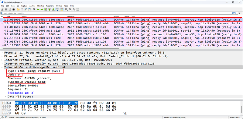
ICMPv6
The figure shows an ICMPv6 echo request packet. The packets in this trace are 6to4 packets.
There are three flavors of Traceroute â€" ICMP based, TCP based and UDP based. ICMP based traceroute uses ICMP echo Requests and changes the Time to Live (TTL) value in the IP header. When packets reach routers along the path, the incoming TTL value is examined. If the incoming TTL value is 1, the router responds with an ICMP Time Exceeded/Time to Live Exceeded in Transit (Type 11, Code 0) (unless this response is disabled on the router). This allows you to find the IP address of the router.
There are three flavors of Traceroute â€" ICMP based, TCP based and UDP based. ICMP based traceroute uses ICMP echo Requests and changes the Time to Live (TTL) value in the IP header. When packets reach routers along the path, the incoming TTL value is examined. If the incoming TTL value is 1, the router responds with an ICMP Time Exceeded/Time to Live Exceeded in Transit (Type 11, Code 0) (unless this response is disabled on the router). This allows you to find the IP address of the router.

ICMP Ping Request â€" no response
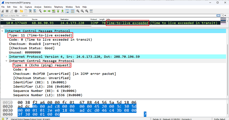
ICMP Time-to-live-exceed
The figures show typical striping that Wireshark displays when default coloring is enabled during a traceroute operation.
ICMPv4 Problems
A common ICMP problem is a no-response echo test, indicating no connection to a destination. To determine the point at which ICMP traffic drops, you need to move the Wireshark system along the path until it reaches the point where packet loss occurs.
However, ICMP itself can help detect many other network issues and security issues. For example, if a DNS query returns Destination Unreachable/Port Unreachable (Type 3/Code 3), either the client is sending DNS queries to the wrong destination or name service is not running on the server.It's tiring.
Another example would be excessive redirects.
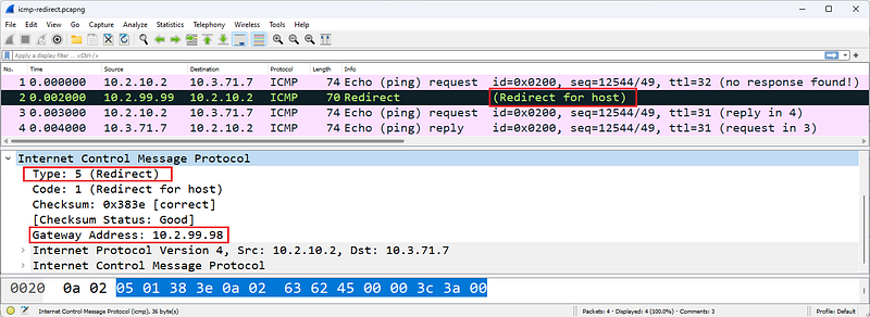
ICMP Redirect
The figure shows an ICMP Redirect packet pointing to another gateway at address 10.2.99.98. This packet is sent when the receiving router determines a better router for the sender. The receiving router creates an ICMP Forwarding (Type 5/Code 1) packet containing the recommended router to use. When received, a host must update its routing table. Redirects should only be sent by routers.
Some ICMP packets, such as ICMP Redirect and ICMP Destination Unreachable packets, contain part of the original packet that triggered the ICMP response. In the figure, the ICMP header is followed by the original IP header of the packet that triggered the ICMP response.
ICMP Destination Unreachable responses to TCP handshake connection requests are unusual because TCP connection requests must elicit either a TCP SYN/ACK or a TCP Reset. The ICMP response to these TCP handshake connection requests is a possible indication that a host's firewall is blocking a port.
ICMPv4 Packet Structure
ICMP packets do not contain a UDP or TCP header - port filtering settings cannot affect ICMP traffic (because it does not use a port). ICMP packets contain only three required fields after the IP header: type, code, and checksum. Some ICMP packets contain additional fields to provide information or details about the message. For example, an ICMP Routing packet must contain the address of the gateway that a host is directed to use. Upon receipt of this packet, a host must add a dynamic route entry to its routing tables and begin using the new routing information immediately.
####Type
The following list defines the types of ICMP messages that can be sent on the network. This list is based on IANA documentation last updated on April 23, 2012. To obtain the most current version of this list, visit www.iana.org/assignments/icmp-parameters.
- Type 0: Echo Reply [RFC 792]
- Type 1: Unassigned
- Type 2: Unassigned
- Type 3: Destination Unreachable [RFC 792]
- Type 4: Source Quench [RFC 792]
- Type 5: Redirect [RFC 792]
- Type 6: Alternate Host Address
- Type 7: Unassigned
- Type 8: Echo [RFC 792]
- Type 9:Router Advertisement [RFC 1256]
- Type 10:Router Solicitation [RFC 1256]
- Type 11: Time Exceeded [RFC 792]
- Type 12: Parameter Problem [RFC 792]
- Type 13: Timestamp [RFC 792]
- Type 14: Timestamp Reply [RFC 792]
- Type 15: Information Request [RFC 792]
- Type 16: Information Reply [RFC 792]
- Type 17: Address Mask Request [RFC 950]
- Type 18: Address Mask Reply [RFC 950]
- Type 19: Reserved (for Security)
- TypeS 20â€"29: Reserved (for Robustness Experiment)
- Type 30: Traceroute [RFC 1393]
- Type 31: Datagram Conversion Error [RFC 1475]
- Type 32: Mobile Host Redirect
- Type 33: IPv6 Where-Are-You
- Type 34: IPv6 I-Am-Here
- Type 35: Mobile Registration Request
- Type 36: Mobile Registration Reply
- Type 37: Domain Name Request
- Type 38: Domain Name Reply
- Type 39: SKIP
- Type 40: Photuris
*Types 41â€"252: Unassigned - Type 253: RFC3692-style Experiment 1
- Type 254: RFC3692-style Experiment 2
####Code
Many ICMP packet types have several possible Code field values. The following list contains descriptions of the more common code fields.
Type 3 Destination Unreachable codes
- Code 0: Network Unreachable â€" The ICMP sender knows the network but believes it is not currently open â€" perhaps it is too far away or only reachable via an unknown route.
- Code 1: Host Unreachable â€" The ICMP sender knows the host but does not receive an ARP response, indicating that the host is currently down.
- Code 2: Protocol Unreachable â€" The protocol identified in the IP header cannot be processed for some reason â€" this response is seen in an IP scan.
- Code 3: Port Unreachable â€" The ICMP sender does not support the port number you are trying to reach â€" a large number of these packets indicates a configuration issue or possibly a UDP port scan; If these packets are sent in response to a TCP handshake attempt, it indicates that the destination port is probably firewalled.
- Code 4: Fragmentation Required and No Fragmentation Set â€" The router's packet is on a link that supports a smaller MTU size.It needed to fragment to transmit over , but the application set the Do Not Fragment bit.
- Code 5: Source Route Failed â€" The ICMP sender cannot use the strict or loose source routing route specified in the original packet.
*Code 6: Destination Network Unknown-The ICMP sender does not have a route entry for the destination network, indicating that the destination network was never an available network.
*Code 7: Destination Host Unknown-There is no host entry indicating that the ICMP sender may not have been on the connected network at all. - Code 8: Source Host Isolated - The ICMP sender (router) is configured not to forward packets from the source. Most routers do not generate this response code â€" they generate codes 0 (network unreachable) and 1 (host unreachable) as appropriate.
- Code 9: Communication with Target Network is Administratively Prohibited â€" The ICMP sender (router) is configured to block access to the intended target network.
- Code 10: Communication with Target Host Administratively Prohibited â€" The ICMP sender (router) is configured to block access to the requested target host.
- Code 11: Unreachable for Target Network Service Type - the Type of Service (TOS) indicator used by the original sender is not available through this router for that network - note that more current networks may not use TOS or Priority - they may use DiffServ instead.
- Code 12: Destination Host Unreachable for Service Type â€" the TOS indicator used by the original sender is not available for that host through this router â€" note that more recent networks may not use TOS or Priority â€" they may use DiffServ instead.
- Code 13: Communication Administratively Prohibited â€" The ICMP sender is not currently available for communication; This may be sent by a fine-grained firewall.
- Code 14: Host Priority Violation â€" the Priority value defined in the sender's original IP header is not allowed (for example, using Flash Override priority) â€" note that more recent networks may not use TOS or Priority â€" they may use DiffServ instead.
- Code 15: Priority Interrupt In Effect â€" The network administrator has set the minimum priority level for service by a router, but a lower priority packet has been received.
Type 5 Redirect Codes
- Code 0: Redirect Datagram for Network (or Subnet) â€" The ICMP sender (router) is not the best way to reach the desired network. The response includes the IP address of the best router to the destination. Dynamically adds a network entry to the original sender's route tables
- Code 1: Redirect Datagram for Host â€" The ICMP sender (router) is not the best way to reach the desired host. The response includes the IP address of the best router to the destination. Dynamically adds a host entry to the original sender's route tables
- Code 2: Redirect Datagram for Service Type and Network â€" The ICMP sender (router) does not provide a route to the destination network using the requested TOS. Dynamically adds a network entry to the original sender's route tables â€" note that more recent networks may not use TOS or Priority â€" they may use DiffServ instead
- Code 3: Redirect Datagram for Service Type and Host â€" The ICMP sender (router) does not provide a route to the destination host using the requested TOS. Dynamically adds a host entry to the original sender's route tables â€" note that more recent networks may not use TOS or Priority â€" they may use DiffServ instead
Type 11 Time Exceeded Codes
- Code 0: Time to Live Exceeded in Transport â€" The ICMP sender (router) indicates that the sender's packet arrived with a TTL of 1. Routers cannot reduce the TTL value to 0 and send a packet
- Code 1: Fragment Reassembly Time Exceeded â€" ICMP sender (target host) did not receive all fragments before the TTL value of the first received fragment expired (retention time in seconds).
Checksum
The checksum field covers only the ICMP header.
ICMPv6 Packet Structure
ICMP packets do not contain a UDP or TCP header - port filtering settings cannot affect ICMP traffic (because it does not use a port). ICMP packets contain only three required fields after the IP header: type, code, and checksum.
####Type
The following list includes what can be sent on the network.Defines ICMPv6 message types. This list is based on IANA documentation last updated on March 28, 2012. To obtain the most current version of this list, visit www.iana.org/assignments/icmpv6-parameters.
- Type 0 Reserved
- Type 1 Destination Unreachable [RFC4443]
- Type 2 Packet Too Big [RFC4443]
- Type 3 Time Exceeded [RFC4443]
- Type 4 Parameter Problem [RFC4443]
- Type 100 Private Experimentation [RFC4443]
- Type 101 Private Experimentation [RFC4443]
- Type 102â€"126 Reserved
- Type 127 Reserved for Expansion of ICMPv6 error messages [RFC4443]
- Type 128 Echo Request [RFC4443]
- Type 129 Echo Reply [RFC4443]
- Type 130 Multicast Listener Query [RFC2710] â€" sent by an IPv6 router to locate general or specific multicast listeners on the local network
- Type 131 Multicast Listener Report [RFC2710] â€" sent by IPv6 hosts to indicate they are listening for a particular multicast address on an interface
- Type 132 Multicast Listener Done [RFC2710] â€" can be sent by an IPv6 node to indicate that it has stopped listening to a multicast address on an interface
- Type 133 Router Solicitation [RFC4861] â€" can be sent when an interface becomes enabled, to request routers to generate Router Advertisements immediately rather than at their next scheduled time
- Type 134 Router Advertisement [RFC4861] â€" used by IPv6 routers to advertise their presence together with various link and Internet parameters either periodically, or in response to a Router Solicitation
message - Type 135 Neighbor Solicitation [RFC4861] â€" sent by a node to determine the link-layer address of a neighbor or to verify that a neighbor is still reachable via a cached link-layer address. Neighbor solicitations are also used for Duplicate Address Detection as seen in Figure 207.
- Type 136 Neighbor Advertisement [RFC4861] â€" a response to a Neighbor Solicitation message. A node may also send unsolicited Neighbor Advertisements to announce a link-layer address change.
- Type 137 Redirect Message [RFC4861]
- Type 138 Router Renumbering [Crawford]
- Type 139 ICMP Node Information Query [RFC4620]
- Type 140 ICMP Node Information Response [RFC4620]
- Type 141 Inverse Neighbor Discovery Solicitation Message [RFC3122]
- Type 142 Inverse Neighbor Discovery Advertisement Message [RFC3122]
- Type 143 Version 2 Multicast Listener Report [RFC3810]
- Type 144 Home Agent Address Discovery Request Message [RFC6275]
- Type 145 Home Agent Address Discovery Reply Message [RFC6275]
- Type 146 Mobile Prefix Solicitation [RFC6275]
- Type 147 Mobile Prefix Advertisement [RFC6275]
- Type 148 Certification Path Solicitation Message [RFC3971]
- Type 149 Certification Path Advertisement Message [RFC3971]
- Type 150 ICMP messages utilized by experimental mobility protocols such as Seamoby [RFC4065]
- Type 151 Multicast Router Advertisement [RFC4286]
- Type 152 Multicast Router Solicitation [RFC4286]
- Type 153 Multicast Router Termination [RFC4286]
- Type 154 FMIPv6 Messages [RFC5568]
- Type 155 RPL Control Message [RFC-ietf-roll-rpl-19.txt]
*Types 156â€"199 Unassigned - Type 200 Private experimentation [RFC4443]
- Type 201 Private experimentation [RFC4443]
- Type 255 Reserved for expansion of ICMPv6 informational messages [RFC4443]
####Code
The following list provides descriptions of the more common ICMPv6 Types that support code domains or have an interesting use.
Type 1 Destination Unreachable Codes
- Code 0: No route to destination - you've made it up to a router, but there's no available routing entry to forward your packet (although the RFC says this could also be sent due to a firewall filter, we'd probably prefer to see the firewall silently discard packets rather than being so thorough)
- Code 1: Communication with the target is administratively prohibited â€" something you would rather not see if you want to silently discard unauthorized packets destined for a protected network
- Code 2: Out of scope of source address â€" this is generated when a packet has a link-local source address and a destination in global scope
- Code 3: Address unavailable â€" this is a general error message for all issues that do not fit into any other code number
- Code 4: Port unreachable â€" same as regular ICMP
- Code 5: Source address input/output policy failed â€" again â€" probably something you don't want to send over the network
- Code 6: Deny path to destination â€" your trafficA general indicator that you cannot reach
- Code 7: Error in Source Redirect Header [RFC-ietf-roll-rpl-19.txt]
Type 2 Packet Too Big Code
- Code 0: This is the only code value currently defined. This packet contains an MTU value and is used for Path MTU discovery.
Type 3 Time Exceeded Codes
- Code 0: Hop limit exceeded during transfer - this matches the standard ICMP message.
- Code 1: Fragment reassembly time exceeded - this matches the standard ICMP message.
Type 4 Parameter Problem Codes
- Code 0: Incorrect header field encountered â€" something in the IPv6 header didn't make sense
- Code 1: Unrecognized Next Header type encountered â€" The Next Header field contained something unusual â€" for a list of assigned IPv6 Next Header/IPv4 Protocol field values, see www.iana.org/assignments/protocol-numbers/protocol-numbers.xml see
*Code 2: Unrecognized IPv6 option encountered - this packet may be sent in response to an IPv6 packet with one or more Extension Headers containing an invalid option.
Type 128 Echo Request Code
- Code 0: This is the only code value currently defined. This packet has an Identifier field that is used to match this Echo Request to an Echo Response.
Type 129 Echo Reply Code
- Code 0: This is the only code value currently defined. This package contains an Identifier field taken from the corresponding Echo Request package
Type 138 Router Renumbering Codes
- Code 0: Router Renumbering Command
*Code 1: Router Renumbering Result - Code 255: Sequence Number Reset
Type 139 ICMP Node Information Query Codes
- Code 0: The data field contains an IPv6 address, which is the Subject of this Query â€" as you can imagine, this type of packet can be used for discovery. For more details, read RFC 4620, "IPv6 Node Information Queries."
- Code 1: The data field contains a name that is the Subject of this Query or is empty as in the case of aNOOP.
- Code 2: The data field contains an IPv4 address, which is the Subject of this Query.
Type 140 ICMP Node Information Response Codes
- Code 0: A successful response. The Response Data field may or may not be empty.
- Code 1: Responder refuses to respond. The Response Data field will be empty.
- Code 2: The Q type of the query is unknown to the Responder. The Response Data field will be empty.
For more information about ICMPv6 type and code numbers, see www.iana.org/assignments/icmpv6-parameters.
References
- Wireshark Network Analysis, Second Edition, Laura Chappell, https://www.chappell-university.com/studyguide
- Trace Files: https://s3.amazonaws.com/book.supplements/StudyGuide_v2/9781893939943_traces-set1b.zip
UDP Wireshark Analysis
Hello, in this article I will try to explain the UDP protocol and its analysis with Wireshark.
What is UDP?
If you see a lot of broadcast/multicast broadcasts in the traffic you capture, it means you have too many UDP-based communications. UDP provides transfer without establishing a connection. Broadcast and multicast traffic flows over UDP. In the UDP header, port fields identify the application using the transport. Because UDP uses a simple 8-byte header consisting of four fields, UDP itself rarely causes problems. UDP is defined in RFC 768, User Datagram Protocol.
Provides UDP connectionless transport service
Common applications that use UDP are DHCP/BOOTP, SIP, RTP, DNS, TFTP and various video streaming applications.
UDP Traffic Analysis
Normal UDP communications, such as DHCP Discover packets, are sent with the destination port number of the requested service. The figure shows the UDP header in a DHCP packet. DHCP uses UDP as the transport protocol. DHCP communications use port 68 as the client port number and port 67 as the server port number.
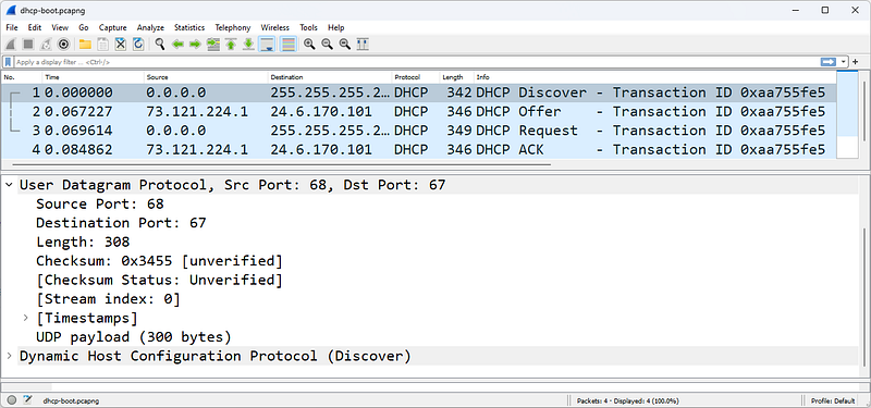
A UDP-based DHCP initialization sequence
Most applications use a default port number for the client side of communication. For example, a DNS query is typically sent to port 53. Source port is a temporary port number.
There are very few problems that occur directly with UDP. One possible problem is traffic blocked based on the UDP port number value. It shows the results of capturing UDP traffic on a network consisting of a firewall that does not forward traffic sent to certain port numbers. In this case, the firewall blocks traffic to ports 161 (SNMP) and 5060 (SIP). Instead of responding with ICMP Destination Unreachable/Port Unreachable (Type 3/Code 3) packets, the firewall silently discards the packets. Your PCAP file only shows UDP traffic; no response is seen.

There is no response to SNMP deficiencies, it is caused by a firewall that filters ports
UDP scans are evident when you see the sorting of UDP packets and ICMP responses using Wireshark's default coloring rules. Again, if a firewall is blocking traffic by port filtering, you may not see ICMP responses.
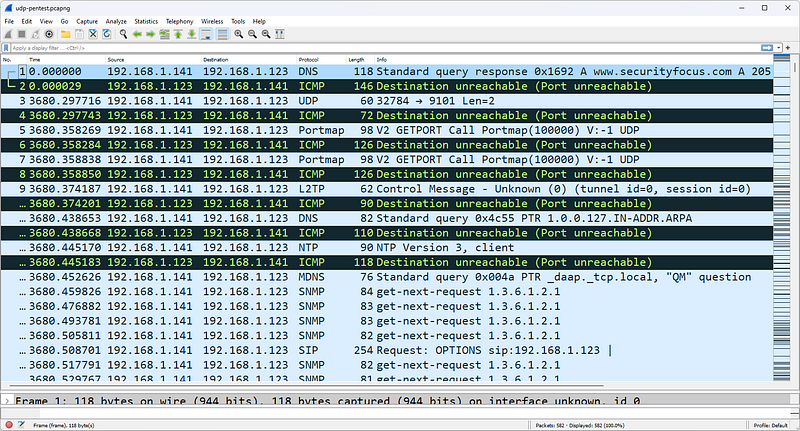
UDP scanning triggers a series of ICMP Destination Unreachable/Port Unreachable responses
The figure shows a UDP scan targeting the address 192.168.1.123. Because each UDP packet triggers an ICMP Destination Unreachable/Port Unreachable response, the UDP scan has not yet found an open UDP port.
UDP Packet Structure
The UDP header is defined by the value 17 (0x11) in the IP header Protocol field.
The UDP header contains only four fields and is always 8 bytes long.
Source Port Field
The source port field has the same purpose in TCP and UDP â€" to open a listening port for response packets and, in some cases, to identify the application or protocol sending the packet.
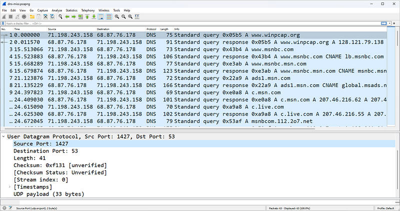
Destination Port Field
This field value identifies the target application or process for the package. In some cases, source and destination port numbers are the same for client and server processes. In other cases, you may find a separate and unique number for client and server operations (as in the DHCP example). Another variation is to allow the client to use temporary port numbers for its own side of the communication and a well-known port number for the server side of the communication.
Length Field
The Length field defines the length of the packet from the UDP header to the end of the valid data. This is a redundant field and is really quite unnecessary in the entire communication process. Consider the following three length fields and their interpretations:
- IP Header Length = 5 (denoted in 4 byte increments)
- The IP header is 20 bytes long.
- IP Total Length Field = 329 bytes
- The data after the IP header is 309 bytes â€" remember that 20 bytes is the IP header.
- UDP Length Field = 309
The data after the IP header (including the UDP header) is 309 bytes. ThisWe found it from the Total Length Field in the IP header. When you remove the 8-byte UDP header, you see that there are 301 bytes of data.
Checksum Field
The checksum is performed on a pseudo-header derived from the contents of the UDP header, the data, and the IP header. The so-called IP header consists of the source address field, the destination address field, the protocol field and the UDP length field. UDP-based communications don't always require a checksum â€" sometimes you'll see this field set to all zeros (0x0000), which tells the recipient that the checksum should not be verified.
UDP Traffic Filters
The capture filter syntax for UDP traffic is simply udp. The display filter syntax is simply udp. Additional UDP display filters are listed below.
- udp.srcport==161 â€" SNMP response (based on port 161)
- udp.dstport==137 â€" NetBIOS Name Service (based on port 137)
- udp.length > 248 â€" UDP packets containing more than 240 data bytes (8 bytes are reserved for the UDP header)
UDP is relatively boring compared to the exciting, complex world of TCP.
References
- Wireshark Network Analysis, Second Edition, Laura Chappell, https://www.chappell-university.com/studyguide
- Trace Files: https://s3.amazonaws.com/book.supplements/StudyGuide_v2/9781893939943_traces-set1b.zip
TCP Wireshark Analysis
Hello, in this article I will try to explain the TCP protocol and its analysis with Wireshark.
What is TCP?
TCP provides connected transport over a connection that begins with a three-way handshake between two devices. Data is sorted and validated to provide automatic recovery of lost packets. UDP can be likened to the standard mail delivery system for a letter or postcard, while TCP can be likened to an express carrier that tracks the delivery of your letter or postcard and sends you notification of receipt.
TCP supports windowing, which is the process of sending multiple data packets sequentially without waiting for an intervening acknowledgment. The size of the window depends on the amount of traffic the network can handle (network congestion rate), the receiver's available buffer space, and the sender's transmission buffer capacity. Most file transfer protocols use TCP to ensure reliable delivery of data.
Offers streaming for applications like TCP, HTTP, HTTPS, email, FTP and more
TCP is covered in RFC 793, but many improvements have been made to the original TCP protocol that should be kept in mind when examining TCP behavior.
TCP Traffic Analysis
Normal TCP communication includes connection establishment, queue monitoring, data loss recovery, and disconnection operations.
TCP Connections
TCP connections are established through a three-way handshake. The basic handshake process requires three packets â€" SYN, SYN/ACK, and ACK.
SYN packets synchronize sequence numbers to ensure that both parties know each other's initial sequence numbers (Initial Sequence Number or ISN). This is how the order of data exchanged between them is kept track of.
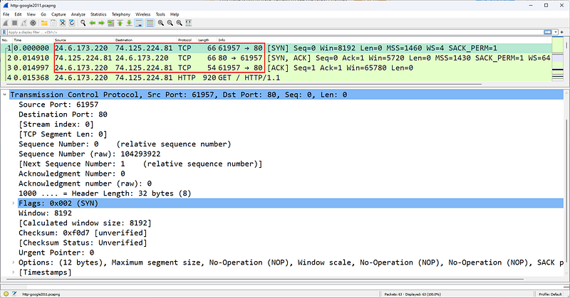
Three-way TCP handshake establishes an FTP connection
In the figure, host 24.6.173.220 establishes a TCP connection to address 74.125.224.81. Packet 1 contains the description [SYN] in the Info column, packet 2 lists [SYN, ACK], and packet 3 lists [ACK]. This recognizable pattern is the TCP three-way handshake used to establish a connection.
TCP connections can be terminated in various ways. An explicit termination uses TCP Resets. An implicit termination uses TCP FIN packets.
When FIN is used, a host sends a FIN packet and enters the FIN-WAIT state until its FIN is acknowledged and the peer sends back its FIN. According to RFC 793, there are actually a few situations that are possible when FIN is used to implicitly terminate a connection.
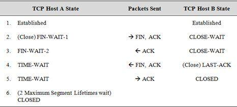
Type netstat -a to find out the current status of TCP connections on a Windows or Linux host. Below is an example of the connection status on a Windows host.
TCP 24.6.173.220:1035 poll:https ESTABLISHED
TCP 24.6.173.220:1071 egw1:https ESTABLISHED
TCP 24.6.173.220:9497 163â€"166:http CLOSE_WAIT
TCP 24.6.173.220:9699 nuq04s07-in-f11:http CLOSE_WAIT
TCP 24.6.173.220:9702 ec2â€"204â€"236â€"130â€"101:http CLOSE_WAIT
TCP 24.6.173.220:9703 ec2â€"204â€"236â€"131â€"42:http CLOSE_WAIT
TCP 24.6.173.220:9706 a184â€"84â€"222â€"33:http CLOSE_WAIT
TCP 24.6.173.220:9798 163â€"166:http CLOSE_WAIT
TCP 24.6.173.220:14717 nuq04s07-in-f5:http CLOSE_WAIT
TCP 24.6.173.220:15582 163â€"166:http CLOSE_WAIT
TCP 24.6.173.220:22167 66â€"151â€"158â€"187:https TIME_WAIT
TCP 24.6.173.220:22168 216â€"115â€"209â€"254:https TIME_WAIT
TCP 24.6.173.220:22169 probe-cgnt-sjc:https TIME_WAIT
TCP 24.6.173.220:22170 probe-cgnt-sjc:https TIME_WAIT
TCP 24.6.173.220:22171 216â€"115â€"209â€"254:https TIME_WAIT
FIN Doesn't Mean "Shut Up"
RFC 793 defines the purpose of the FIN bit as indicating that no more data will arrive from the sender. This does not prevent the recipient of the FIN packet from sending additional data, which is allowed.
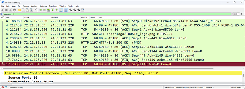
TCP Reset is used to explicitly close a TCP connection
You may also see a Reset used to explicitly terminate a TCP connection. The Reset may be preceded by FINs or the Reset may occur on its own. The figure shows an HTTP connection established by 24.6.173.220. In a FIN packet, the server sends a packet with the FIN bit set, indicating that it has no more data to send. The client acknowledges the response and sends a packet with the FIN bit set. Finally, the server sends the connection in the last packet.explicitly sends a TCP Reset to terminate.
TCP Packet Tracing and Recovery
The sorting/validation process monitors the order of packets and detects and recovers missing sections.
During the handshake process, each side of the connection selects its own starting sequence number (Initial Sequence Number). Both parties increment this sequence number by the amount of data contained in each packet. When analyzing the ranking/approval process, this simple equation is used:

Here's a quick example of how a sequential communication can happen with simple terms/numbers:
The Confirmation Number field is only incremented when data is received. By default, Wireshark uses Relative Sequence Numbering, which starts sequence number values ​​at 0 for easier readability. Instead of displaying a sequence number like 402691989, Wireshark starts with a sequence number of zero because it is easier to work with smaller numbers. If you want to see the actual sequence numbers, disable TCP Relative Sequence Numbers and Window Scaling in the TCP preferences (remember, the Acknowledgment Number field contains the value of the next expected sequence number from the other side).
Once agreement is reached, sequence numbers only increase by the number of actual data bytes sent. In this example, the client is the first peer to send data (a request to retrieve the home page on a web server).
TCP Sequence and Acknowledgment numbers keep track of data being exchanged

First Connection
The TCP communications shown in the figure can be seen in the file named http-espn2011.pcapng. In this file, the user connects to www.espn.com and is notified that the content has been permanently moved to go.espn.com. The client then connects to go.espn.com.

Second Link
The beginning of this second connection and the Sequence/Acknowledgment Number field values are shown in the Figure.
TCP is capable of detecting packet loss (based on missing sequence numbers) and recovering by requesting missing data segments (receiving side) or by timing out and resending unacknowledged segments (sending side).
When the recipient notices that the expected sequence number is not on the package, they assume the package is lost. At this point, the receiver sets the Acknowledgment Number field to ACK to the next expected sequence number from the peer.
High latency paths may cause more than three identical ACKs
Receiving more than three ACs will trigger retransmission. For example, when the sequence is skipped as shown in the figure, the receiver sends an ACK with 112750 in the Confirmation Number field. If the sequence number is not 112750, additional ACKs (with 112750 in the Acknowledgment Number field) will be sent when additional data is received. Wireshark marks these as Duplicate ACKs.
TCP senders maintain a TCP Retransmission Timeout (RTO) value to determine when a packet not acknowledged by a TCP peer should be retransmitted. If a data packet is sent and is not acknowledged before the RTO timer expires, the TCP sender can retransmit the packet using the sequence number of the original packet.

The HTTP server retransmits a packet when the retransmission timeout value is reached
The figure shows a server that resends the data packet after waiting for an ACK and does not receive it before the RTO expires. Another retransmission is sent approximately 600 ms later. Using TCP's backoff algorithm, the intervening time is doubled with each retransmission attempt until the packet is acknowledged or the sending TCP host gives up after five retransmissions.
TCP provides a method of flow control to ensure that traffic is not sent over a connection known to be heavy or to an overloaded host.
The throughput of TCP communications depends on network congestion. congestion defines the number of bytes pending (confirmed) at a time. This is essentially a flow control mechanism implemented by the sender. congestion is not a setting; It is determined dynamically based on two key factors:
- Receiver's TCP buffer space reported
- Sender's transmission buffer capacity
- Amount of traffic allowed on the network (network clickdepending on immediacy/packet loss)
congestion will always be lower than these three values. For example, assume that on an Ethernet network, a receiver advertises a 65,535-byte frame, but the connection regularly experiences packet loss before ever taking advantage of the peer's 65,535 receive buffer.
The actual congestion is not 65,535 bytes but a lower value depending on what the network will support. The process for determining congestion after packet loss is described in detail in RFC 2001.
TCP Problems Analysis
There are many problems that can occur at the TCP layer, from problems with the handshake process to packet loss, TCP connection drops, frozen windows.

TCP connection rejected with RST/ACK
We start with TCP handshake problems. The figure shows a TCP connection rejection. In Figure 235, the first packet of the handshake (SYN) receives a Reset (RST/ACK) response. Unable to connect. If the handshake process is not completed successfully, data cannot be exchanged between hosts.
An excessive number of failed TCP connection attempts may indicate a TCP scan.
A failed TCP connection due to packet loss
The figure shows another problem with the handshake process. When we examine the figure, we can see the following:
- Handshake looks normal; SYN, SYN/ACK, ACK in packets 3â€"5. Notice that in the first packet of the handshake (SYN), the client's sequence number, 67.161.32.69, is shown as 0, a relative sequence number identified by Wireshark. The next packet sent from this client (packet number 5) shows that the client's sequence number is now 1, even though the client has not sent any data in the SYN packet. The TCP specification (RFC 793, Transmission Control Protocol) defines that the first data packet after SYN packets must increment the Initial Sequence Number (ISN) by 1.
- After the handshake operation, the client sends a packet containing 14 bytes of data to the server and sets the Push (PSH) and ACK bits on packet 6.
- Packet 7 is the first indication that something is wrong. The client's RTO value has expired while waiting for an ACK to arrive at packet 6. Packet 7 is a retransmission of packet 6.
- Packet 8 is also a retransmission. The server resent the SYN/ACK packet from the TCP handshake. It looks like the server did not receive the third packet of the handshake process. The server sets the Acknowledgment Number field value to 1 to request the handshake ACK packet from the client.
- The server constantly requests the third packet of the handshake. However, the client sent two packets with Sequence Number 1. The client retransmits the first data packet of the handshake instead of the last packet.
This problem cannot be solved by itself. The server will not accept 14 bytes of data until it sees that the handshake is resolved properly. To create a new connection attempt, the application that initiated the TCP connection to the RWhois (Routing Whois) service on port 4321 must be restarted.
TCP Packet Structure
The TCP header is typically 20 bytes long, but the TCP header supports an Options field that can increase the header length.
Source Port Field
TCP source port is the listening port number open on the sender.
Destination Port Field
TCP destination port is the destination port number open on the receiver.
Stream Index [Wireshark Field]
Flow Index is not an actual field in the TCP header. The Stream Index value is defined by Wireshark and can be used to quickly filter a TCP conversation.
Sequence Number Field
This field contains a number that uniquely identifies the TCP segment (the data following the TCP header is called a TCP 'segment'). This sequence number provides an identifier for the TCP segment and allows receivers to determine when parts of a communication stream are missing. The sequence number increases with the number of data bytes contained in each packet.
Next Expected Sequence Number [Wireshark Field]
This field appears only in packets that contain data â€" this field does not appear in SYN packets or simple ACK packets. Wireshark examines the current packet Sequence Number and adds the number of data bytes to provide that number.
Acknowledgment Number Field
The Confirmation Number field is the next sequence number expected from the other side of the communication.It shows . An Acknowledgment Number field that is never incremented by a host simply indicates that no data was received by that host.
Data Offset Field
This defines the length of the TCP header. It is defined in 4-byte increments, so a value of 5 in this field indicates that the TCP header is 20 bytes long. We need this field because the TCP header length may vary depending on the TCP header options used. The TCP option field is often used to establish the Maximum Segment Size (MSS) during TCP connection setup.
Flags Field
The following list describes the flags used in the TCP header:
- Reserved: These three bits are set to zero.
- Nonce: The Nonce field works with ECN fields in the IP header. This functionality is described in RFC 3540, Robust Explicit Congestion Notification (ECN) Signaling with Nonces.
- Congestion Window Reduced (CWR): delay is set by the data sender to notify the data receiver that Congestion has been reduced.
- URG (Urgent): Indicates that the Urgent Pointer field should be examined; The Immediate Pointer field is located after the TCP Checksum field and is set to 0x0000 when not in use. The Immediate Pointer field is processed only when this bit is set.
- ACK (Acknowledgment): Confirmation package
- PSH (Push): Skip buffering and push data directly to the network Do not buffer incoming data â€" push directly to the application
- RST (Reset): Explicitly close the connection
- SYN (Synchronize): Synchronize sequence numbers â€" used in the handshake process
- FIN (Finish): Process completed, connection termination
Window Field
This field indicates the size of the TCP receiver buffer in bytes. A window size of 0 indicates that the receiver has no available buffer space. The maximum value that can be displayed in this two-byte area is 65,535. Window scaling (created during the TCP handshake process) allows hosts to use larger window sizes. For all packets with a Window Size field value less than 65535, the display filter is tcp.window_size < 65535.
Checksum Field
TCP checksum is performed on the contents of the TCP header and data (data link padding is not included), as well as a pseudo-header derived from the IP header. See RFC 793 for more information.
Urgent Pointer Field
This field is valid only if the URG bit is set. If the URG bit is set, the receiver must examine this field to see where to look/read first in the packet. This is not a common function. The display filter for all packets containing the Urgent Pointer field is tcp.urgent_pointer. Wireshark will not display this field unless the urgent bit is set to 1.
Filtering TCP Traffic
In TCP Traffic, the capture and display filter syntax is simply tcp.
- tcp.srcport==21 â€" FTP response (assuming FTP is running on port 21)
- tcp.dstport==80 â€" Traffic directed to port 80 (HTTP mostly works on port 80)
- tcp.hdr_len > 20 â€" TCP headers containing one or more options
- (tcp.window_size < 1460) && (tcp.flags.fin==0) && (tcp.flags.reset==0) â€" TCP window size smaller than an MSS in a packet with the RST bit not set â€" this slows down the data transfer process; windows updates are required to recover â€" for example, look for such packages in the http-download-good.pcapng trace file.
- !(tcp.flags.cwr==0) || !(tcp.flags.ecn==0) â€"Packets with the Congestion Reduced flag or ECN-Echo flag set.
- tcp.options.mss_val < 1460 â€" TCP MSS setting is less than 1,460 bytes (this will be seen during the handshake process)
- tcp.options.wscale_val â€" TCP window scale option available in TCP header.
- tcp.analysis.flags â€" Packets flagged with TCP problems or notifications (does not work if Analyze TCP Sequence Numbers is disabled in TCP preferences)
- tcp.analysis.lost_segment â€" A lost segment was detected before this packet â€" one of many individual TCP analysis flags available. Use the autocomplete feature (tcp.analysis.) - include period - or Expressions to display other TCP analysis flags
References
- Wireshark Network Analysis, Second Edition, Laura Chappell, https://www.chappell-university.com/studyguide
- Trace Files: https://s3.amazonaws.com/book.supplements/StudyGuide_v2/9781893939943_traces-set1b.zip
[TR] Hidden Tunnels (C&C) Analysis with Wireshark
Hello, in this article I will talk about HTTP tunneling techniques.
In the field of computer security, the term "Hidden Tunnels" generally refers to hidden or unauthorized network connections used for various purposes such as malicious data exfiltration, command and control (C&C), or bypassing network detection. These secret tunnels help attackers hide their activities and bypass security measures.
HTTP/HTTPS Tunneling
HTTP/HTTPS tunneling is a technique used to bypass network security measures. This method is accomplished by encapsulating non-HTTP traffic inside HTTP or HTTPS packets. HTTP/HTTPS tunneling can be used for legitimate purposes, such as accessing websites or services trapped in environments with restrictive web filtering policies, but it can also be used for malicious activities such as data exfiltration or remote control of compromised systems.
- Encapsulation: In HTTP/HTTPS tunneling, non-HTTP traffic is encapsulated into HTTP or HTTPS packets. This means packaging another application or protocol's data like regular web traffic.
- Sending: The encapsulated data is then sent to a remote server or destination over an HTTP or HTTPS connection. The target server treats incoming HTTP/HTTPS requests and responses as normal web requests, making it difficult for network security devices to identify the true nature of the traffic.
- De-encapsulation: On the receiving side, HTTP/HTTPS packets are decompressed and the original non-HTTP data is extracted. This data is then processed or executed as required.
From a security perspective, the use of HTTP/HTTPS tunneling means that traditional security devices may have difficulty detecting and blocking such covert communication channels. To combat this problem, organizations often use advanced threat detection and prevention solutions that can examine traffic more deeply, looking for anomalies and signs of suspicious behavior. Additionally, security policies and network monitoring are important to identify and mitigate risks associated with HTTP/HTTPS tunneling.
Using HTTP or HTTPS protocols, cybercriminals can create hidden tunnels within web traffic, allowing them to exfiltrate data or control infected systems.
HTTP/HTTPS tunneling is a technique used to route or tunnel HTTP (Hypertext Transfer Protocol) or HTTPS (HTTP Secure) traffic over a network to another server. This type of tunneling can pose a significant problem, especially in terms of network security.
How to do HTTP/HTTPS Tunneling?
HTTP/HTTPS tunneling is used to transmit or redirect HTTP or HTTPS requests or responses, normally considered web traffic, to another server. They can use several different methods for this:
- HTTP Proxy Servers: Users or malware access the internet through an HTTP proxy server. This proxy server receives users' requests, forwards them to the target server, and tunnels the responses back to the user.
- VPN (Virtual Private Network): VPNs are a type of tunneling technology that users use to provide privacy and security on the internet. By creating an encrypted tunnel between the VPN client and server, HTTP or HTTPS traffic can pass through the tunnel.
- SSH (Secure Shell): SSH is a method used to create a secure communication channel between two devices on the network. This is used to encrypt and secure data transmission between computers. SSH tunnel is widely used, especially when secure data transmission over the internet is required.
HTTP/HTTPS Tunneling Analysis
HTTP/HTTPS tunneling is an issue that must be carefully monitored for network security. Firewalls, IDS/IPS (Intrusion Detection System/Intrusion Prevention System) systems, and other security measures can be used to monitor and detect such tunneling traffic. Additionally, user education and security policies can help reduce risks associated with HTTP/HTTPS tunneling.
DNS Tunneling
DNS tunneling sends data over the DNS protocol, which is a protocol not designed for data transfer.It is a method used to reach. This is done for the purpose of carrying other types of data within DNS packets or communicating with another server. DNS tunneling can pose a significant problem, especially in terms of network security. One reason for this is that DNS pacts can pass through security products such as firewalls without getting stuck.
How is DNS Tunneling done?
DNS tunneling is accomplished by hiding DNS queries and responses within normal DNS traffic.
- The attacker registers a domain name like badsite.com. The server of the domain points to the attacker's server where the tunneling program is installed.
- The attacker infects a computer with malware, usually behind a company's firewall. Since DNS requests are always allowed in and out of the firewall, the infected computer is allowed to send a query to the DNS resolver.
- DNS resolver is a server that forwards IP address requests to the root and top-level domain servers. This directs the query to the attacker's command and control server where the tunneling program is installed.
- A connection has now been established between the victim and the attacker via the DNS resolver. This tunnel can be used to exfiltrate data or other malicious purposes. Since there is no direct connection between the attacker and the victim, it is more difficult to track down the attacker's computer.
DNS Tunneling
DNS Tunneling Analysis
wireshark
DNS tunneling can pose a serious threat to network security, so firewalls, IDS/IPS systems, and DNS controls should be used to protect against such attacks. Additionally, a good security policy and DNS traffic monitoring and analysis capabilities can help detect such threats.
ICMP Tunneling
ICMP tunneling or ICMP covert channels is a method used to create covert communication channels within ICMP (Internet Control Message Protocol) packets. ICMP is typically used for network troubleshooting and error reporting, but attackers can surreptitiously use this protocol for data transmission. This technique is also known as "ICMP tunneling" because it involves encapsulating non-ICMP traffic within ICMP packets to bypass network security controls.
How ICMP tunneling works:
- Encapsulation: ICMP tunneling involves encapsulating non-ICMP data or traffic within ICMP "echo request" and "echo reply" packets, which are typically used for network diagnostic purposes, such as ICMP "ping" requests.
- Transmission: The encapsulated data is then transmitted as ICMP traffic between the sender and receiver. The sender and receiver are often compromised systems or devices under the control of an attacker.
- De-encapsulation: At the receiving end, ICMP packets are decompressed to extract the original non-ICMP data, which is then processed or used as required.
While ICMP tunneling can be used for malicious purposes, it can also have legitimate applications when used for network diagnostics in certain scenarios.
From a security perspective, ICMP tunneling can present challenges in detection and prevention. Network security solutions should use advanced anomaly detection techniques to identify abnormal or unauthorized ICMP traffic patterns. Additionally, organizations should implement network segmentation and access control to limit the use of ICMP traffic and reduce the risk of covert channel abuse.
ICMP (Internet Control Message Protocol) tunneling is a technique that allows cyber attackers to transmit and scan data by bypassing network security measures. ICMP is a protocol used to transmit error messages and other control messages between network devices. ICMP tunneling is used to tunnel data through these control messages.
How to do ICMP tunneling?
ICMP tunneling may involve the following basic steps:
- Tunnel Initiation: First, cyber attackers typically initiate an ICMP tunnel to gain access to a target server or network. This is usually done using a malware or attack tool.
- Sending Data: Attackers hide data within ICMP packets. This data may contain information that needs to be transmitted to the target server or network.
- Sending ICMP Packets: Data,Once hidden within ICMP packets, these packets are sent to the destination server or network. These packets may appear to be normal ICMP traffic.
- Receiving Side: A receiving party on the target server or network intercepts incoming ICMP packets and extracts obfuscated data from them.
Cyber attacks and ICMP tunneling:
Cyber attackers can use ICMP tunneling for malicious purposes. Here are some examples:
**Data Exfiltration**: Attackers can hide the data they need to exfiltrate to the target server or network using ICMP tunneling. This can make it easier for sensitive information to be stolen.
**Blocking and Filtering Bypass**: Some network firewalls or filters can be used to block or limit ICMP traffic. ICMP tunneling can be used to bypass such blocking.
Scanning and Reconnaissance: Attackers can use ICMP tunneling to detect vulnerabilities in the target network and scan targets.
ICMP tunneling can pose a serious threat to network security because it can be difficult to monitor and block such traffic. Therefore, network firewalls and IDS/IPS (Intrusion Detection System/Intrusion Prevention System) systems must be well configured to detect and block ICMP tunneling traffic. Additionally, regular security audits and security policies can also help guard against such threats.
Resources
HTTP Wireshark Analysis
Hello, in this article I will try to explain the HTTP protocol and its analysis with Wireshark.
What is HTTP?
Hypertext Transfer Protocol (HTTP) is called "distributed hypermedia information distribution application". HTTP is the application used when a person browses the internet. HTTP uses a request/response model.
HTTP and HTTPS use TCP transport
HTTP v1.0 is not used as frequently as HTTP v1.1, the current version in use. HTTP v1.1 is covered in RFC 2616, Hypertext Transfer Protocol â€" HTTP/1.1.
HTTP Traffic Analysis
Normal HTTP communications use the request/response communication style. Clients make requests to HTTP servers and servers respond with Status Codes.

HTTP uses a request/response pattern
Once the TCP connection is successfully established, the client makes an HTTP GET request for "/". The server responds with a 200 OK status code and starts sending the contents of the www.facebook.com homepage to the client.
All HTTP Status Codes seen in http-facebook.pcapng are good - all 200 OK. The HTTP Status Code Registry is kept at www.iana.org/assignments/http-status-codes. Available Status Codes are listed below.
1xx Informational
- 100 Continue [RFC2616]
- 101 Switching Protocols [RFC2616]
- 102 Processing [RFC2518]
2xx Success
- 200 OK [RFC2616]
- 201 Created [RFC2616]
- 202 Accepted [RFC2616]
- 203 Non-Authoritative Information [RFC2616]
- 204 No Content [RFC2616]
- 205 Reset Content [RFC2616]
- 206 Partial Content [RFC2616]
- 207 Multi-Status [RFC4918]
- 208 Already Reported [RFC5842]
- 226 IM Used [RFC3229]
3xx Redirection
- 300 Multiple Choices [RFC2616]
- 301 Moved Permanently [RFC2616]
- 302 Found [RFC2616]
- 303 See Other [RFC2616]
- 304 Not Modified [RFC2616]
- 305 Use Proxy [RFC2616]
- 306 Reserved [RFC2616]
- 307 Temporary Redirect [RFC2616]
- 308 Permanent Redirect [RFC-reschke-http-status-308â€"07]
4xx Client Error
- 400 Bad Request [RFC2616]
- 401 Unauthorized [RFC2616]
- 402 Payment Required [RFC2616]
- 403 Forbidden [RFC2616]
- 404 Not Found [RFC2616]
- 405 Method Not Allowed [RFC2616]
- 406 Not Acceptable [RFC2616]
- 407 Proxy Authentication Required [RFC2616]
- 408 Request Timeout [RFC2616]
- 409 Conflict [RFC2616]
- 410 Gone [RFC2616]-
- 411 Length Required [RFC2616]
- 412 Precondition Failed [RFC2616]
- 413 Request Entity Too Large [RFC2616]
- 414 Request-URI Too Long [RFC2616]
- 415 Unsupported Media Type [RFC2616]
- 416 Requested Range Cannot be Satisfied [RFC2616]
- 417 Expectation Failed [RFC2616]
- 422 Unprocessable Entity [RFC4918]
- 423 Locked [RFC4918]
- 424 Failed Dependency [RFC4918]
- 425 Reserved for WebDAV â€" see IANA list [RFC2817]
- 426 Upgrade Required [RFC2817]
- 428 Precondition Required [RFC6585]
- 429 Too Many Requests [RFC6585]
- 431 Request Header Fields Too Large [RFC6585]
5xx Server Error
- 500 Internal Server Error [RFC2616]
- 501 Not Implemented [RFC2616]
- 502 Bad Gateway [RFC2616]
- 503 Service Unavailable [RFC2616]
- 504 Gateway Timeout [RFC2616]
- 505 HTTP Version Not Supported [RFC2616]
- 506 Variant Also Negotiates (Experimental) [RFC2295]
- 507 Insufficient Storage [RFC4918]
- 508 Loop Detected [RFC5842]
- 510 Not Extended [RFC2774]
- 511 Network Authentication Required [RFC6585]
If an HTTP client has recently visited a page and that page is cached locally, the client can send the IfModified-Since parameter and provide the date and time when the previous page was downloaded. If the server responds with 304 Not Modified, the server will not resend the already cached page. This is an important part of HTTP to understand when analyzing HTTP performance.
HTTP Statistics
Wireshark monitors HTTP statistics for payload distribution, packet counters, and HTTP requests. Statistics | Select HTTP and choose the type of statistics you are interested in.
An option is provided to apply a display filter to the statistics. For example, if you have a trace file that contains web browsing sessions to many hosts, you can filter "http.host==www.wireshark.org" to examine statistics for web browsing sessions only to www.wireshark.org.You can apply it.

Statistics
HTTP Load Distribution lists HTTP requests and responses by server. Expanding the HTTP Requests by HTTP host section lists the hosts contacted and the number of request packets sent to each.
The HTTP Load Distribution statistic is an excellent resource for identifying website redirects and dependencies.

HTTP payload distribution
When we browse to www.espn.com in the figure, we see the HTTP redirects and dependencies.

HTTP Packet Counter
HTTP Packet Counter is very valuable because it lists the Status Code
answers. Detecting 4xx Client Error or 5xx Server Error responses is simple. The figure shows the HTTP Packet Counter for another browsing session to www.espn.com (httpespn2007.
pcapng). We can see some HTTP 301 and 302 redirects and a 404 Not Found response.

HTTP Requests
HTTP Requests lists each item requested from each HTTP server. In the figure, we examine HTTP Requests Requests sent to www.espn.com during our Web browser session.
HTTPS Traffic Analysis
Your web analysis will likely include analysis of HTTPS communications. At the beginning of a secure HTTP conversation, a standard TCP handshake is followed by a secure handshake.
RFC 2818 defines the use of HTTP over Transport Layer Security (TLS) for secure communications. RFC 2246 details Transport Layer Security version 1.0, which is based on SSL version 3.0. Although there is little difference between TLS 1.0 and SSL 3.0, the two are not interoperable
HTTPS communication begins with a TCP handshake on the port to be used for secure communication. In our example, we are using standard HTTPS port 443. If you use another port for SSL/TLS traffic, add these ports to the HTTP preferences setting for SSL/TLS ports. Port 443 is defined by default.

What is FTP? Use the ssl.record.content_type==22 display filter to view the TLS handshake
In HTTPS communications, a TLS handshake occurs after the TCP handshake. The TLS handshake consists of a series of packets with a content type value of 22. Use the ssl.record.content_type==22 filter to view TLS handshake packets as shown in Figure.
The TLS handshake allows peers to agree on security parameters for exchanging data and verify their identities. Additionally, errors during the handshake process are transmitted in TLS handshake packets.
This handshake process includes the following types of traffic:
- Session identifier: identifies a new or ongoing session
- Peer certificate: X509 certificate
- Compression method: compression method for data before encryption
- Cipher spec: defines the data encryption algorithm
- Master secret: 48 bytes of secret information shared between client and server
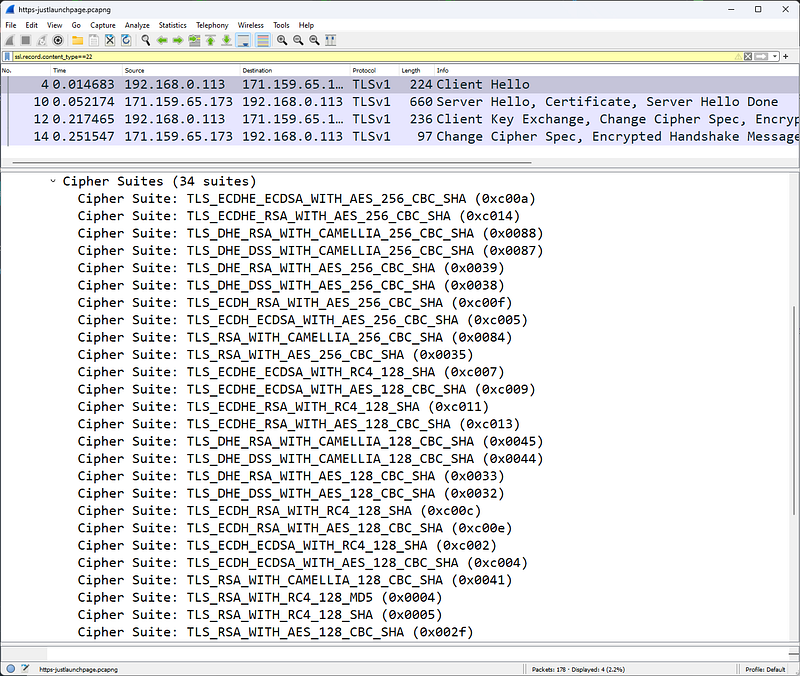
The client lists 34 supported cipher suites; the server will choose which one to use
The first packet of the TLS handshake, Packet 4 in the Figure, is a Client Hello as specified in the handshake protocol field. The client also indicates that it is using TLS version 1.0.
In the Random section, this package includes the Universal Coordinated Time (UTC) in the client provided in UNIX format. The Session ID field is set to 0, indicating that this is a new session. If the Session ID field contains a non-zero value, this is a restarted session.
This packet also contains 28 random bytes. This random set of bytes will then be sent again during the handshake, but will then be encrypted with the server's public key
The client provides a list of cipher suites supported by the browser. In this case, the client supports 34 cipher suites and lists them all in the client hello packet as shown in Figure. Ultimately, the server will decide which cipher suite to use, butn upper password is the client's choice.
Extensions add functionality to TLS. The presence of extensions is detected as there are bytes following the Compression Methods field at the end of the Client Hello packet.
An extension provides the server name, in this case www.bankofamerica.com. The server name extension allows the client to create a secure connection to a virtual server that can be hosted on a machine that supports multiple servers on a single IP address.

Pack 10
In packet 10, the Server responds with a packet of three functions:Â
Server Hello, Certificate and Server Hello Done.
In the Random part, the server provides 28 random bytes and a 32-byte Session ID value to allow the client to reconnect later. This random set of bytes will then be sent again during the handshake, but will then be encrypted with the client's public key. These random bytes are used for key generation.
Among the 34 cipher suites offered, the server chose TLS_RSA_with_RC4_128_MD5 (0x0004), which means:
- The RSA public key algorithm will be used to verify certificate signatures and exchange keys.
- RC4 encryption algorithm will be used to encrypt exchanged data.
- The 128-bit MD5 hash function will be used to verify the content of exchanged messages.
This second packet of the handshake process also contains the certificate from the server. Within the same packet is the phrase Server Hello Done to indicate that the server has completed the Hello process.
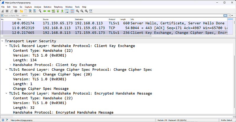
Pack 12
Packet 12 shown in the figure is the next packet from the client. This packet indicates that the client calculates a premaster secret from both client and server random values. The Change Cipher Spe assignment indicates that all messages coming from the client will be encrypted using the defined keys and algorithms.
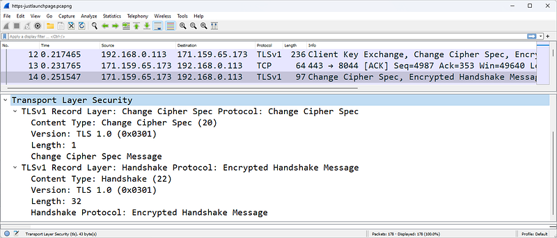
Pack 14
In packet 14, the unencrypted part of the handshake process ends with the server indicating that all messages it sends will also be encrypted.
Decrypting HTTPS Traffic
In order for Wireshark to decrypt HTTPS traffic, we need to have the RSA key and configure Wireshark to use it.
To decrypt this data, we need the private key of the server certificate. To retrieve the private key, you need to access the server; You cannot retrieve the private key from the client side of the communication. Since our example uses a browsing session to Bank of America's website and we have no way of obtaining the key, we will focus on another HTTPS trace file provided with the key.
In November 2009, PhoneFactor's Steve Dispensa and Marsh Ray wrote an 8-page overview of the security issues surrounding the TLS renegotiation process. Security issues have been demonstrated against recent versions of Microsoft IIS and Apache HTTPD. In essence, the described renegotiation attack method is used to inject malicious code into the "secure" connection.
In the example below, we are working with the client_init_renego.pcap file provided as an attachment to the PhoneFactor document. Additionally, PhoneFactor has provided an RSA key named ws01.mogul.test.key.
Enter the path to the RSA key file to decrypt traffic
To decrypt HTTPS traffic, we copied the RSA key to a \keys directory on the local Wireshark host. In order for Wireshark to recognize the key, we must configure the SSL preferences to recognize the speech we want to decrypt and point to the \keys directory. Wireshark's RSA keys list setting includes the IP address of the server, the port used for encrypted communication, the name of the application being encrypted, and the key name as well as the path to the key.
The figure shows the settings used to decrypt this file. Notice that the Protocol column indicates TCP, SSL, or TLSv1. We cannot see decrypted traffic yet.
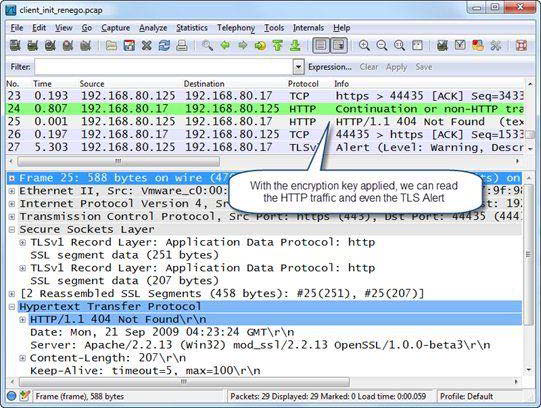
Once the key is configured and applied, we can see the HTTP communication clearly
The figure shows the results of applying the switch. protocolIn the ol column we still see TCP and TLSv1, but we also see HTTP listed for decrypted traffic. In addition, we can now right-click on an HTTP packet listed in the Packet List pane and select Follow SSL Stream to see the communication clearly
When you decrypt TLS traffic (just like when you decrypt WLAN traffic), a tab appears just below the Packet Bytes pane, as shown in the figure. Click the Decrypted SSL data tab to view the decrypted traffic in the Packet Bytes pane. This tab will only appear when you (a) decrypt the traffic and (b) make the Packet Bytes pane visible.
HTTP Errors Analysis
HTTP communication problems can occur due to problems with site name resolution, problems with the TCP connection process, HTTP requests for non-existent pages or elements, packet loss, and congestion on the HTTP server or client.
Everyone has typed in the wrong website address at one time or another. If the site name cannot be resolved, you cannot access the site. This creates a DNS Name Error. It's important to pay attention to DNS traffic when analyzing web browsing problems.
Additionally, HTTP connection problems can occur when the HTTP daemon is not running on the web server. When the HTTP daemon is not running on the server, the server responds to the client's SYN with a TCP RST/ACK. Connection cannot be established.
Additionally, HTTP connection problems can occur on the web server when multiple failed HTTP connection attempts create a stripe pattern in Wiresharkdaemon.
This should be monitored carefully as the SYN â€" RST/ACK pattern is seen during a port scan operation as shown in the figure.
If the HTTP client successfully connects to the HTTP server, but then requests a page that does not exist, HTTP 404 Not Found errors are generated by the web server.
Some redirect services replace the standard 404 Not Found message with suggested links or redirect the HTTP client to another site entirely. Create a coloring rule for HTTP client and server errors using http.response.code >= 400.

frys.com server responds with an internal server error
The figure shows an issue when opening a list of laptops for sale on the www.frys.com website. We were able to resolve the IP address of the site and the page exists. By following the TCP flow we can see that the server responds with the page title. However, laptop items are not displayed on the page; page is blank.
When we look at the trace file, we can see that the www.frys.com web server is reporting an internal server error. This is not a problem with the customer's system or network. This issue is most likely caused by a database issue in Fry's web services infrastructure.
Open the http-fault-post.pcapng file and set the Time column to Seconds Since Previous Displayed Packet. Note that there is a large delay before packet 29. Be careful here. The FIN bit is set in the 29th packet. This indicates that the client has finished sending information to the server. These packets (and packets with the Reset bit set) can be triggered long after the user has finished receiving the required data. The user does not notice this delay, so do not waste your time removing delays before packets marked with the FIN (or Reset) bit.
The client's POST fails, indicating a web server issue
We are trying to fill out an online form as follows (http-fault-post.pcapng). But when the Submit button is clicked, the client system seems to crash. In this case, we can look at the HTTP traffic and observe the 403 Forbidden status code coming from the server. When we follow the TCP stream, we see clear text and HTML tags with more information about the state (we removed the HTML tags):
"The page cannot be displayed â€" you attempted to execute a CGI, ISAPI, or other executable program from a directory that does not allow programs to be executed."
Again, the issue does not appear to be a client issue and we do not consider TCP transfer errors to be an issue. The problem is on the server.
When troubleshooting web browsing issues, look for TCP errors before focusing on HTTP traffic.
HTTP Packet Structure
HTTP packets are of variable length. In this section we list some important fields in the HTTP packet structure. HTTP requests consist of a Method that defines the purpose of the HTTP request. HTTP responses contain a numeric response code called a Status Code.
An HTTP GET request packet for the Facebook homepage
The figure shows a GET request for the main Facebook page. The GET request contains the name of the target host, details about the browser sending this GET request, and information about what data types and format the browser will accept.
HTTP Methods
Methods, also called HTTP methods, define the purpose of the HTTP packet.
- GET: Retrieves information identified by the URI (Uniform Resource Indicator) field
- HEAD: Retrieves metadata about the requested URI
- POST: Sends data to HTTP server
- OPTIONS: Sets the options associated with a resource
- PUT: Sends data to HTTP server
- DELETE: Deletes the resource identified by URI
- TRACE: Invokes a remote loopback so the client can see what the server received from the client; this is rare because many companies disable it to protect against Cross-Site Tracking vulnerability
- CONNECT: Connects to a proxy device.
####Host
The host field is required in all HTTP/1.1 request messages. The host field identifies the target internet host and port number of the requested resource. In our previous example, the host is www.facebook.com. If no port number is specified, the default port for the service (for example, port 80 for HTTP) is used.
Request Modifiers
HTTP requests and responses use request modifiers to provide details about the request. Listed below are the more commonly used request modifiers:
- Accept: Acceptable content types
- Accept-Charset: Acceptable character sets
- Accept-Encoding: Acceptable encodings
- Accept-Language: Acceptable languages
- Accept-Ranges: The server can accept range requests
- Authorization: Authentication information for HTTP authentication
- Cache-Control: Caching directives
- Connection: Connection type preferred by the user agent
- Cookie: HTTP cookie
- Content-Length: Length of the request body (bytes)
- Content-Type: Mime type of the body (used with POST and PUT requests)
- Date: Date and time the message was sent
- Expect: Defines the server behavior expected by the client
- If-Match: Take action if the information provided by the client matches
- IfModified-Since: Provide date/time of cached data; if up to date 304 Not Changed
- If-Range: Request for missing information range
- If-Unmodified-Since: Send only if not modified since specific date/time
- Max-Forwards: Limit the number of transmissions via proxies or gateways
- Proxy-Authorization: Authorization credentials for proxy connection
- Range: Claim only part of an asset
- Referer: The address of the previous website that links to the current website
- TE: Transfer encodings accepted
- UserAgent: User agent â€" typically browser and operating system
- Via: Passed proxies
Filtering HTTP/HTTPS Traffic
The filtering syntax for HTTP or HTTPS traffic is tcp port http or tcp port https.
- http.request.method=="GET" or http.request.method=="POST" â€" HTTP GET or POST requests
- http.response.code > 399 â€" HTTP 4xx or 5xx (client or server errors)
- http contains "IfModified-Since" â€" Determining whether a client has already cached a page.
- http.host=="www.wireshark.org" â€" Target host www.wireshark.org
- http.user_agent contains "Firefox" â€" The HTTP client uses the Firefox browser.
- http.referer contains "wireshark.org" â€" HTTP client reached current location from a link in wireshark.org
- tcp.port==443 â€" SSL-Secure Socket Layer (secure session)
- ssl.record.content_type==22 â€" TLSv1 handshake
- ssl.handshake.type==1 â€" TLSv1 Client Hello in handshake
- ssl.handshake.type==16 â€" TLSv1 Client Key exchange
- ssl.record.content_type==20 â€" TLSv1 Change Cipher Spec
- http.content_type contains "ocsp" â€" Online Certificate Status Protocol (OCSP) is used
Exporting HTTP Objects
To save downloaded objects when using HTTP, click File | Export Objects| Select HTTP. When you export HTTP objects, the original object name is preserved.
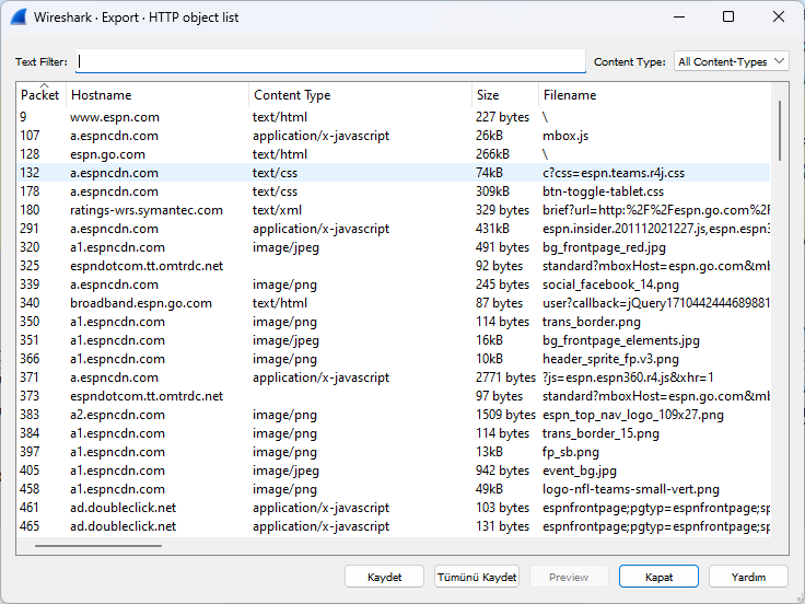
We can export objects downloaded from a site
We can save objects to our computer via this menu.